Image pickup module, manufacturing and assembling methods of the same, endoscope and capsule type endoscope using the same

A technology of a camera assembly and an assembling method, which is applied in the directions of endoscope, installation, photography, etc., can solve the problem of generating stray light, and achieve the effect of preventing stray light and preventing the mixing of garbage

Inactive Publication Date: 2009-09-09
OLYMPUS CORP
View PDF2 Cites 25 Cited by
  • Summary
  • Abstract
  • Description
  • Claims
  • Application Information

AI Technical Summary

Problems solved by technology

However, in this case, since the runner mark 71c is exposed without being shielded from light by the light shielding member 73, as described above, light enters the exposed portion and is emitted as scattered light from the inner peripheral surface of the flange portion 71a, and becomes scattered light. And part of the emitted light is incident on the imaging element 80, resulting in the generation of stray light

Method used


Image

  • Image pickup module, manufacturing and assembling methods of the same, endoscope and capsule type endoscope using the same
  • Image pickup module, manufacturing and assembling methods of the same, endoscope and capsule type endoscope using the same
  • Image pickup module, manufacturing and assembling methods of the same, endoscope and capsule type endoscope using the same

Examples


no. 1 approach

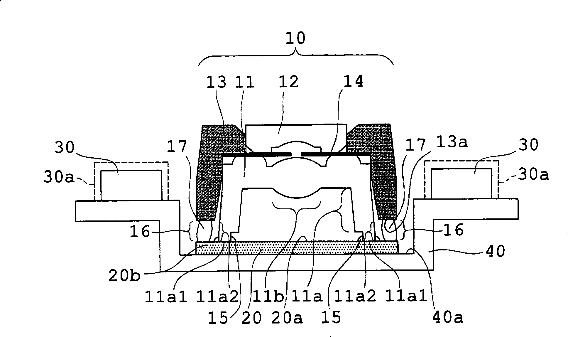
[0055] figure 1 It is an explanatory diagram showing a schematic configuration of the imaging module according to the first embodiment of the present invention.

[0056] The imaging module of the first embodiment includes an imaging lens 10 , an imaging element 20 , and an illumination element 30 . in addition, figure 1 Reference numeral 14 in the figure is a luminance aperture, reference numeral 30a is a light emitting surface (light emitting range) of the lighting element, and reference numeral 40 is a substrate. The imaging lens 10 is configured by including lenses 11 , 12 and a frame member 13 .

[0057] The lens 11 is manufactured by injection molding, and has the flange part 11a and the lens part 11b integrally. The gate during injection molding is provided on the flange portion 11a at a position close to the imaging element 20, and a gate trace (not shown) remains on the flange portion 11a corresponding to the gate. The frame member 13 is made of light-shielding m...

no. 2 approach

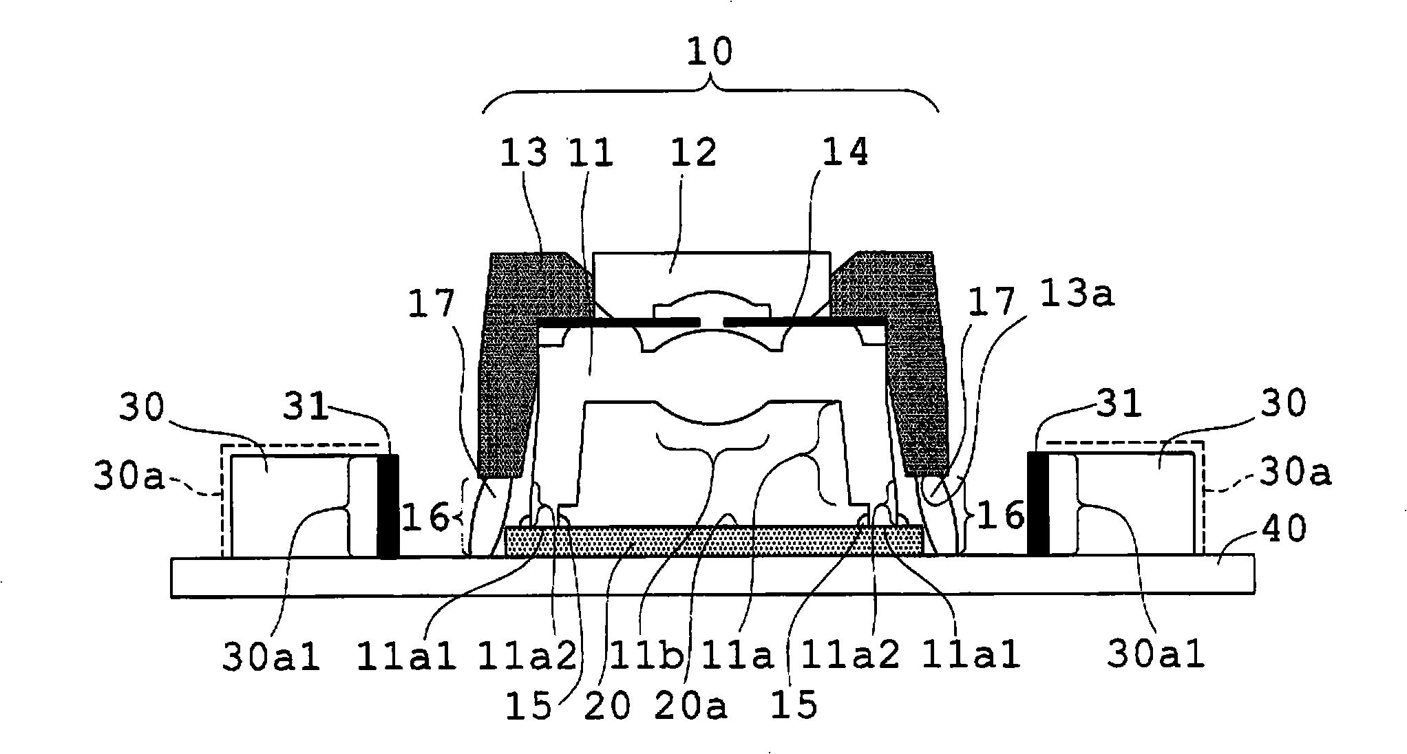
[0064] figure 2 It is an explanatory diagram showing a schematic configuration of an imaging module according to a second embodiment of the present invention. In the imaging module of the second embodiment, the substrate 40 is formed as a plane that holds the imaging element 20 and the lighting element 30 at the same height, and is not shielded from light by the frame member 13 of the flange portion as in the imaging module of the first embodiment. The exposed portion 11a2 of the light emitting device 30 is located at substantially the same position as the light emitting surface (light emitting range) 30a of the lighting element 30 . Instead, in the imaging module of the second embodiment, the range 30a1 of the lighting element 30 capable of irradiating the exposed portion 11a2 is shielded by the light-shielding member 31, so that the emitted light from the light emitting surface 30a of the lighting element 30 does not directly reach the flange. The exposed portion 11a2 of t...

no. 3 approach

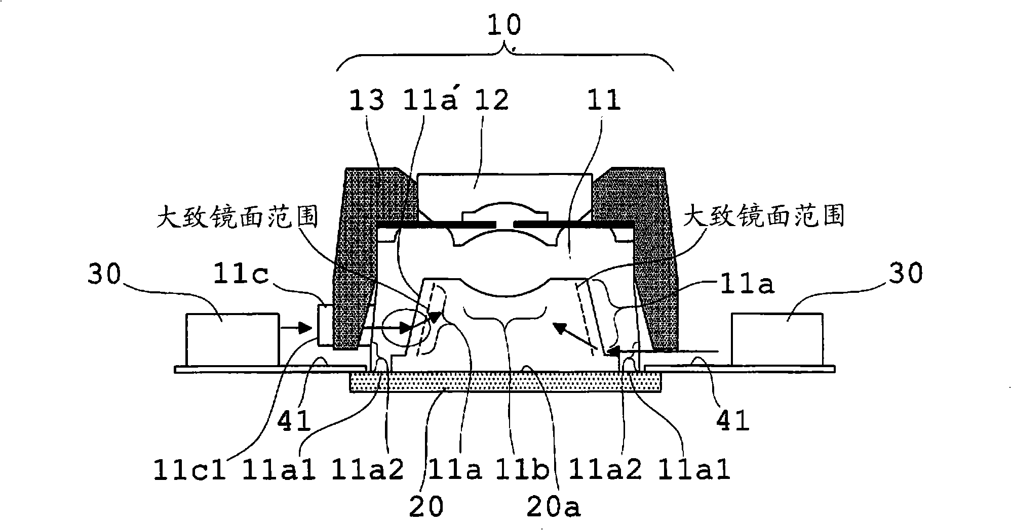
[0068] image 3It is an explanatory diagram showing a schematic configuration of an imaging module according to a third embodiment of the present invention. In the imaging module of the third embodiment, the imaging element 20 and the illuminating element 30 are mounted on the support plate 41 with the support plate 41 interposed therebetween, and are arranged on substantially the same plane. Moreover, the frame member 13 is formed so that the runner trace 11c formed in the outer peripheral surface of the flange part 11a may pass, and the runner trace 11c may be exposed to the exterior of the frame member 13. As shown in FIG. Therefore, the emitted light from the light emitting surface of the lighting element 30 directly reaches the exposed portion 11a2 of the flange portion 11a that is not shielded from light by the frame member 13 and the end surface 11c1 of the runner mark 11c. Instead, in the imaging module of the third embodiment, the inner peripheral surface 11a' of the...


PUM


Abstract

The invention provides an image pickup module and manufacturing and assembling methods of the same, endoscope and capsule type endoscope using the same. An image pickup module comprises a lens assembly including a lens having a flange part, and a frame component for shading a circumferential surface excluding a neighborhood of a top portion of the flange part in the lens; an image pickup element which the top portion of the flange part touches; and an illumination element arranged around said lens assembly and said image pickup element. It is constituted so that exit light from a luminescence surface of said illumination element may not reach directly to an exposed portion which is not shaded by said frame component of the flange part.

Description

technical field [0001] The present invention relates to an imaging unit having a lens integrally having a flange portion, a method of manufacturing the imaging unit, a method of assembling the imaging unit, an endoscope using the imaging unit, and an imaging unit using an imaging unit, which are used in portable information terminals and endoscopes. Capsule-type endoscope for modules, in particular, to a small and thin camera module suitable for endoscopes, a method for manufacturing the camera module, a method for assembling the camera module, an endoscope using the camera module, and a capsule-type endoscope using the camera module looking glass. Background technique [0002] Conventionally, for imaging devices used in mobile phones, endoscopes, etc., especially in imaging devices used in endoscopes, etc., size reduction and weight reduction have been sought in order to reduce the burden on patients as much as possible and improve operator operability. Therefore, a unitiz...

Claims


Application Information

Patent Timeline
Patent Type & Authority Applications(China)
IPC IPC(8): G02B7/00G02B13/00G02B23/24G03B15/02A61B1/05G02B7/02G03B15/00G03B15/03G03B17/02H04N5/225H04N5/335
CPCA61B1/041G02B7/02
Inventor 折原达也金野光次郎福堀仁志
Owner OLYMPUS CORP
Why Eureka
Try Eureka