Field emission cold cathode

A cold cathode and cathode technology, applied in the field of vacuum tubes, can solve the problems of reducing energy efficiency of heaters, increasing system volume, weight and complexity, etc.

Inactive Publication Date: 2009-09-09
THE UNITED STATES OF AMERICA AS REPRESETNED BY THE SEC OF THE AIR FORCE
View PDF0 Cites 2 Cited by
  • Summary
  • Abstract
  • Description
  • Claims
  • Application Information

AI Technical Summary

Problems solved by technology

Additionally, heaters reduce energy efficiency and increase system size, weight and complexity

Method used


Image

  • Field emission cold cathode

Examples


Embodiment Construction

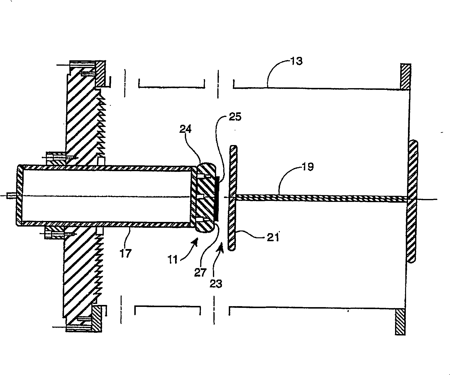
[0015] The accompanying drawing is a schematic diagram of experimental equipment for testing the field emission cold cathode 11 of the present invention, and shows a cross section of the cold cathode 11 . The apparatus includes a vacuum chamber 13 and a cathode mounting table 17 . The rod 19 protrudes into the vacuum chamber 13 and can be retracted and extended relative to the cold cathode 11 . Anode 21 is mounted on one end of rod 19 . Gap 23 is the distance separating cathode 11 and anode 21 and is adjustable by retracting or extending rod 19 .

[0016] The cold cathode 11 consists of a high voltage bushing 24 , a carbon velvet material 25 and a cathode surface 27 . As will be described in detail later, the carbon velvet material 25 is treated with a low work function cesium salt and bonded to the cathode surface 27 . The carbon velvet material 25 consists of high aspect ratio carbon fibers embedded perpendicular to the matrix material. Specific materials of this type ar...


PUM

PropertyMeasurementUnit
Thicknessaaaaaaaaaa

Abstract

The invention relates to a field emission cold cathode, in particular to a field emission cold cathode (11) used in a vacuum tube. A carbon velour material (25) is composed of carbon fibers with high aspect ratio, which are embedded in a direction vertical to a base material. The tips and / or bar part of the carbon velour material (25) are / is coated with low-function cesium salt. The base material of the carbon velour material (25) is bonded to a cathode surface (27). The cold cathode (11) emits electrons when an electric field is applied even at an operating temperature lower than 90 DEG C.

Description

[0001] This application is a divisional application of the Chinese invention patent application with the application number 02829338.X (PCT / US2002 / 021283), the application date being July 18, 2002, and the invention name being "field emission cold cathode". [0002] U.S. Government Statement of Interest [0003] This invention is made so that, pursuant to subsection 1(a) of the Executive Order, all rights, titles and interests therein, including rights in foreign countries, are vested in the Government of the United States of America, represented by the Secretary of the Air Force. technical field [0004] The invention belongs to the field of vacuum tubes, in particular to field emission cold cathodes used as electron emitters in vacuum tubes. Background technique [0005] Cathodes are electron emitters used in many types of vacuum tubes, such as cathode ray tubes used in televisions and various microwave tubes used in radar and communications. All of these cathodes must be...

Claims


Application Information

Patent Timeline
IPC IPC(8): H01J9/02H01J1/304H01J23/04
CPCH01J1/304H01J2201/30446H01J9/025
Inventor D·A·小施弗勒
Owner THE UNITED STATES OF AMERICA AS REPRESETNED BY THE SEC OF THE AIR FORCE
Why Eureka
Try Eureka