
Pressure power generating device and method thereof

A technology of pressure power generation and pressure device, which can be used in electromechanical devices, wind power generation, wind turbines, etc., and can solve problems such as difficulty

Inactive Publication Date: 2009-09-16
陈小明
View PDF1 Cites 3 Cited by
  • Summary
  • Abstract
  • Description
  • Claims
  • Application Information

AI Technical Summary

Problems solved by technology

This method has such defects: the driving device of this method must be pressured by regular and periodic force-applying objects in order to maintain continuous rotation and then generate mechanical energy, but it is generally difficult to find the pressure of force-applying objects in public places It is regular, periodic and continuous, so this method is difficult to implement

Method used


Image

  • Pressure power generating device and method thereof
  • Pressure power generating device and method thereof
  • Pressure power generating device and method thereof

Examples


Embodiment 1

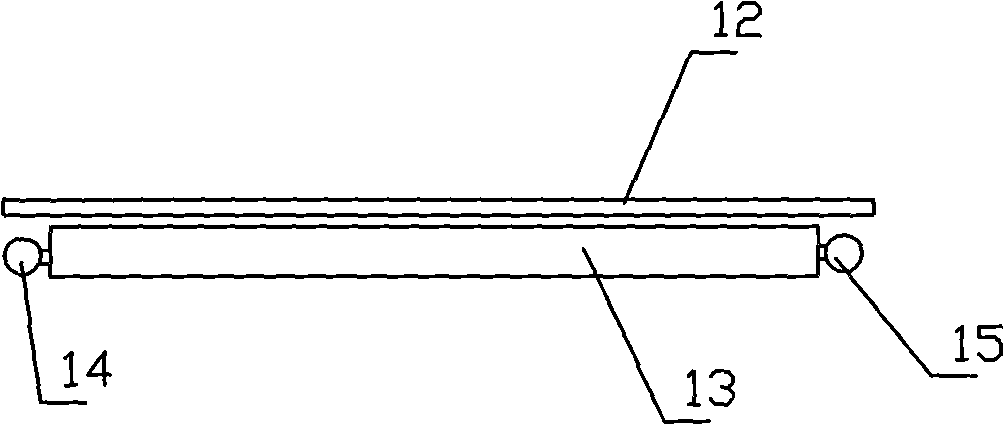
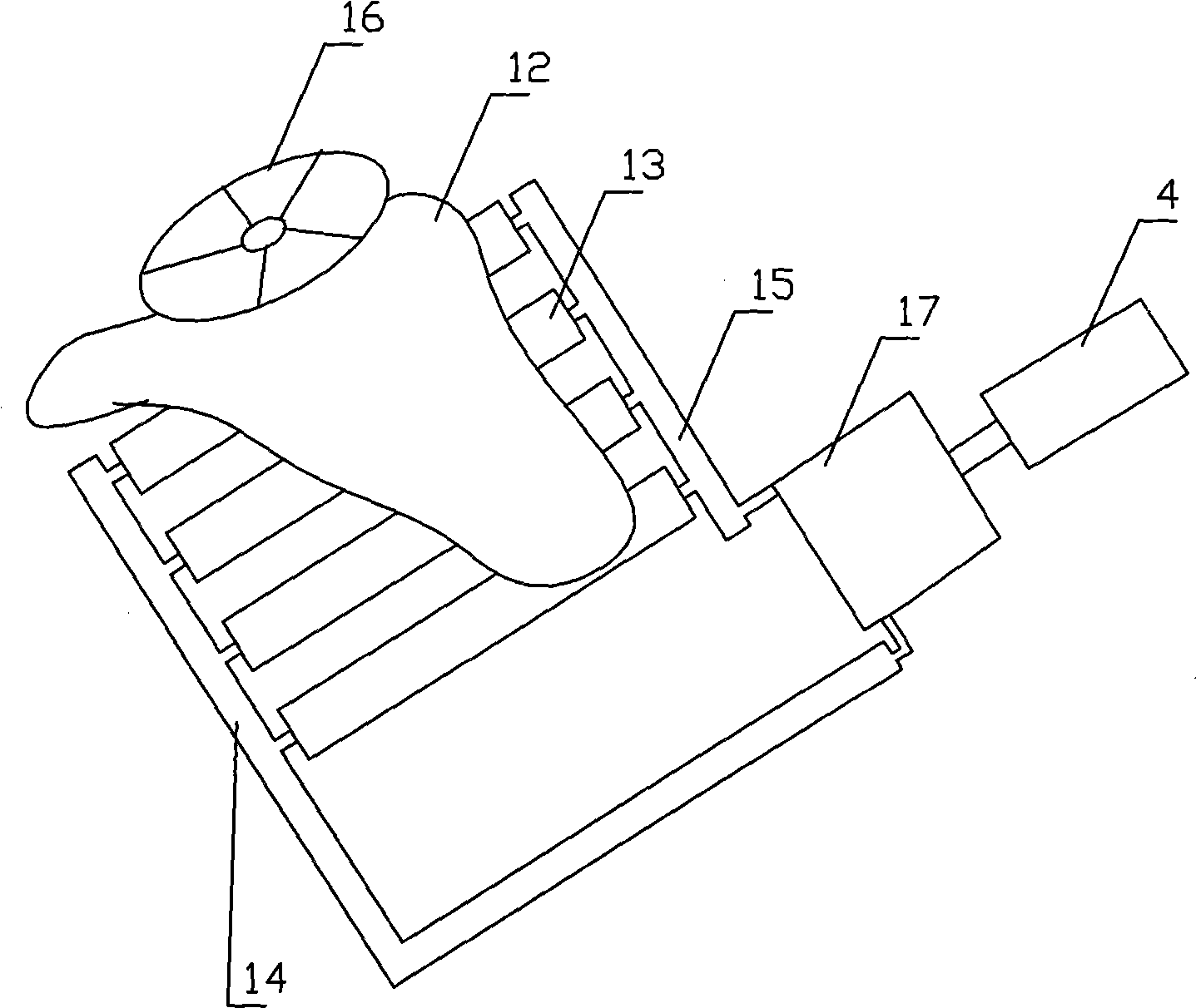
[0022] Embodiment 1: as figure 1 figure 2 As shown, the pressure generating device includes a mechanical energy collector, a hydraulic turbine 17, and a generator 4. The mechanical energy collector is composed of a deformable plastic surface layer 12 and a plurality of tubular pressure devices 13 under the surface layer. Each tubular pressure device 13 Placed parallel to each other, the tubular presses 13 are filled with liquid and made of elastic materials. The head end of each tubular pressor communicates with the low-pressure pipe 14, the tail end of each tubular pressor communicates with the high-pressure pipe 15, and the high-pressure pipe communicates with the hydraulic turbine 17. The liquid inlet is communicated, the low-pressure pipe is communicated with the liquid outlet of the liquid turbine, and the output rotating shaft of the liquid turbine 17 is connected with the rotating shaft of the generator.

[0023] When the wheel 16 of the automobile passes through the ...

Embodiment 2

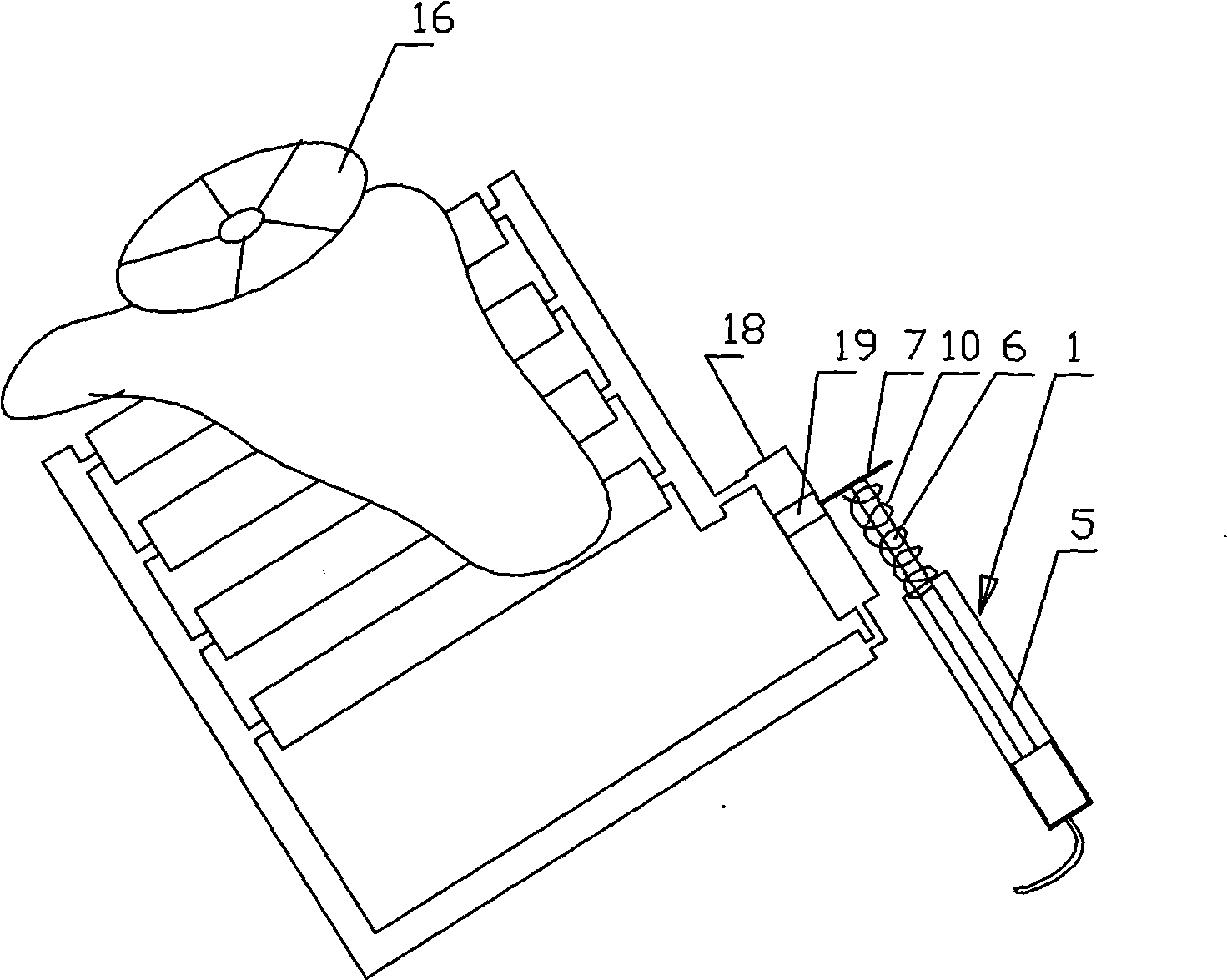
[0024] Embodiment 2: as image 3 , Figure 4 As shown, the pressure power generation device includes a mechanical energy collector, a gas pump device 1 for converting mechanical energy into gas internal energy, a storage tank 2 for storing high-pressure gas, a gas turbine 3 and a generator 4 . The mechanical energy collector is composed of a deformable plastic surface layer and a plurality of tubular pressure devices under the surface layer. The tubular pressure devices are placed parallel to each other. The tubular pressure devices are filled with liquid and made of elastic materials. The head end of each tubular pressure device It communicates with the low-pressure pipe, the tail end of each tubular pressure device communicates with the high-pressure pipe, the high-pressure pipe communicates with the liquid inlet of the piston pump 18, and the low-pressure pipe communicates with the liquid outlet of the piston pump. The air pump device is a conventional traditional air pump...


PUM


Abstract

The invention discloses a pressure power generating device which is characterized by comprising a mechanical energy collector and a power generator. The mechanical energy collector consists of a deformable plastic surface layer and a plurality of strips of tubular pressure gauges below the surface layer. All the tubular pressure gauges are parallel mutually; the tubular pressure gauges are filled with liquid and are made of elastic materials; and the head ends of the tubular pressure gauges are communicated with a low-pressure tube and the tail ends thereof are communicated with a high-pressure tube. The power generating device can be applied in places with more people and more vehicles; passing of irregular and aperiodic stream of people and stepping of irregular and aperiodic stream of people and passing of vehicles can lead a storage to collect energy; therefore, the pressure power generating method has low requirements to the condition of places for implementation and is easy to implement. The invention also discloses another power generating device and power generating method.

Description

technical field [0001] The invention relates to a pressure power generation device and a power generation method applied to the device. Background technique [0002] Electric energy is an indispensable energy source in people's daily life and industrial production. The traditional methods of generating energy include: thermal power generation, hydropower generation, wind power generation and nuclear power generation. It is a long-term pursuit of people to generate electric energy in different ways. Chinese patent application number 200510130231.5 discloses a method of pressure power generation, which includes the following steps: first, the force-applying object exerts downward pressure on the driving device through its own gravity, and then obtains the torque through the moment arm of the driving device and Mechanical energy is generated by doing work, and then the mechanical energy is transmitted to the speed increaser by the transmission device, and the speed increaser i...

Claims


Application Information

Patent Timeline
IPC IPC(8): F03G7/00F03B13/00F03D9/02H02K7/18F03D9/17
CPCY02E10/72Y02E70/30
Inventor 陈小明
Owner 陈小明
Learn More