LED light fitting reflecting cover
A technology of LED lamps and reflectors, applied in the direction of light sources, reflectors, point light sources, etc., can solve the problems of bright spots and spots in blind spots, low light efficiency utilization, uneven illumination, etc., to achieve wide coverage and high light efficiency. High utilization rate and wide irradiation range
- Summary
- Abstract
- Description
- Claims
- Application Information
AI Technical Summary
Problems solved by technology
Method used
Image
Examples
Embodiment 1
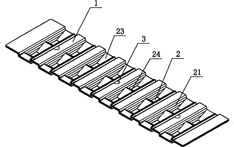
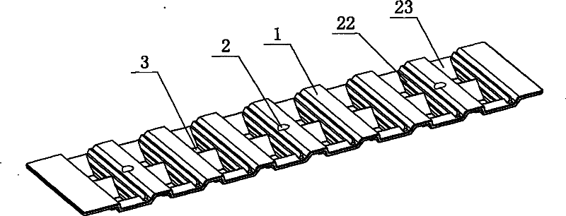
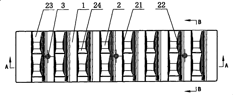
[0023] Such as Figure 1 to Figure 6 As shown, the present invention includes a substrate 1, on which a plurality of grooves 2 arranged in an array are arranged, and the surroundings of the grooves 2 are reflective surfaces, and the reflective surfaces include first reflective surfaces opposite to each other laterally. 21 and the second reflective surface 22 and the third reflective surface 23 and the fourth reflective surface 24 that are vertically opposite, the first reflective surface 21 includes four arc-shaped curved surfaces distributed along the longitudinal direction, and the second reflective surface 22 includes three A curved curved surface longitudinally distributed, the curved curved surface of the first reflective surface 21 is a convex surface, the curved curved surface of the second reflective surface 22 is a concave surface, the convex surface and the concave surface are both spherical surfaces, of course, The arc-shaped curved surfaces of the first reflective ...
Embodiment 2
[0025] Such as Figure 7 As shown, the height of the light pole 5 of the LED lamp of the present embodiment is 10 meters, the bottom end of the light pole 5 is located at the edge of the motorway, and the top of the light pole 5 has a horizontal bar protruding in the road and the length is 1 meter. , the lamp is located at the front end of the crossbar, the installation elevation angle of the lamp is γ=15°, the motor vehicle road width is W2=12 meters, there is a sidewalk on each side of the motor vehicle road, its width W1=W3=4 meters, and the total road width is W1 +W2+W3=20 meters. The lateral main luminous angle ε=64° of the reflector of the LED lamp of the present invention, which completely covers the 12-meter motorway, and the redundant angles δ1=9° and δ2=4° cannot illuminate the effective road surface, so this embodiment The luminous angle utilization rate of (180°-4°-9°) / 180°=92.8%, it can be seen that the light efficiency utilization rate of this embodiment is very...
Embodiment 3
[0028] Such as Figure 9 As shown, in this embodiment, four reflectors of LED lamps are combined together for use in lamps, and there is also a certain angle between the reflectors of LED lamps, and the four reflectors of LED lamps are combined together to form a bent shape , which is more conducive to the adjustment of the light distribution angle and range of the lamp as a whole.
PUM
 Abstract
Description
Claims
Application Information
 - R&D
- Intellectual Property
- Life Sciences
- Materials
- Tech Scout
- Unparalleled Data Quality
- Higher Quality Content
- 60% Fewer Hallucinations
Browse by: Latest US Patents, China's latest patents, Technical Efficacy Thesaurus, Application Domain, Technology Topic, Popular Technical Reports.
© 2025 PatSnap. All rights reserved.Legal|Privacy policy|Modern Slavery Act Transparency Statement|Sitemap|About US| Contact US: help@patsnap.com


