Fire-fighting link remote control device and control method

A technology of remote control equipment and fire-fighting linkage, applied in the direction of program control, computer control, general control system, etc., can solve the problems of delaying the timing of disaster relief, wiring, checking lines, inconvenient maintenance, high cost of engineering wires, etc., to save wires Cost and engineering construction cost, contact signal control is stable and reliable, and the effect of reducing operation errors

Inactive Publication Date: 2009-09-16
JIANGSU YINJIA GROUP
View PDF0 Cites 16 Cited by
  • Summary
  • Abstract
  • Description
  • Claims
  • Application Information

AI Technical Summary

Problems solved by technology

[0003] 1. The existing fire remote control equipment uses one button to correspond to the start and stop functions of one fire equipment, but one button needs four wires to control one equipment, which belongs to the multi-wire control mode. If there are many fire equipment, then The cost of wires in the project is very high, and it is inconvenient to wire, check and maintain
[0004] 2. The existing fire remote control equipment does not have intelligent detection technology, and there is no online detection, fault detection, startup indication, feedback indication, etc. for remote fire protection equipment. To ensure accurate control, misoperation is often caused. For example, the remote fire fighting equipment is in a fault state, and the control equipment also issues a command to start it, resulting in misoperation and damage to the equipment
[0005] 3. In emergency situations such as fire, if there are many fire-fighting linkage equipment on the scene that need to be started quickly at the same time, the traditional fire-fighting remote control equipment cannot meet this requirement because of the control method that one button corresponds to one fire-fighting equipment, and the timing of disaster relief will be delayed.

Method used


Image

  • Fire-fighting link remote control device and control method
  • Fire-fighting link remote control device and control method
  • Fire-fighting link remote control device and control method

Examples


Embodiment Construction

[0036] The present invention will be described in further detail below in conjunction with the accompanying drawings and specific embodiments.

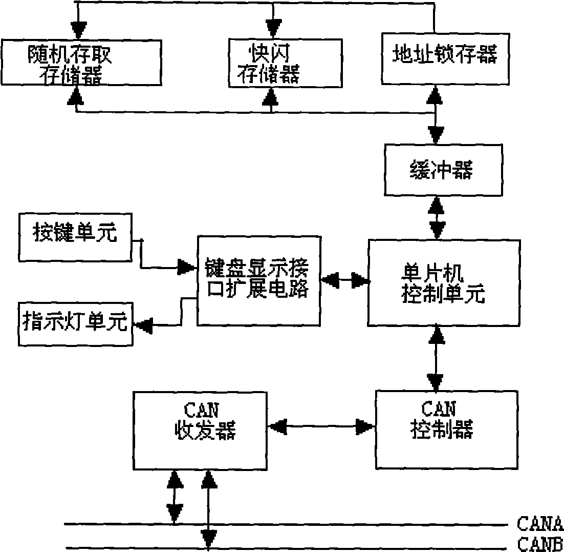
[0037] Such as figure 1 As shown, the fire-fighting linkage remote control device is composed of a key unit, an indicator light unit, a single-chip microcomputer control unit, a data storage expansion unit, a CAN bus signal modulation unit, and a keyboard display interface expansion circuit.

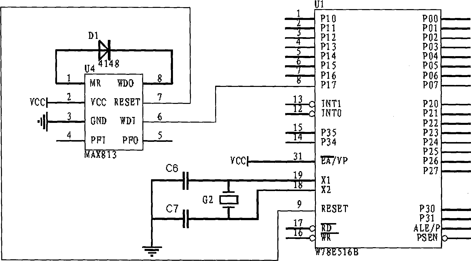
[0038] The single-chip microcomputer control unit is composed of a single-chip microcomputer, a clock circuit, and a reset circuit, such as figure 2 As shown, the model of MCU U1 is W78E516B, its pins 18 and 19 are connected to the clock circuit, the MCU reset circuit is composed of reset chip U4 and diode D1, the model of reset chip U4 is MAX813, the model of diode D1 is 4148, and the reset chip of U4 Pin 1 is connected to the positive pole of diode D1, pin 8 is connected to the negative pole of diode D1, pin 7 is connected to the reset termi...


PUM


Abstract

The invention discloses a fire-fighting link remote control device and a method. The device and the method adopt a CAN bus for communication to save conducting wires, can detect and display various working states of fire-fighting devices, realize starting or stopping remote fire-fighting devices through a key, and perform linkage of various fire-fighting devices according to requirements. The technical proposal of the invention has the key points that the fire-fighting link remote control device consists of a key unit, an indicator light unit, a singlechip control unit, a data memory expansion unit, a CAN bus signal modulation unit, and a keyboard display interface expander circuit; the singlechip control unit consists of a singlechip, a clock circuit and a reset circuit; the data memory expansion unit consists of a buffer, an address latch, a random-access memory and a flash memory; the CAN bus signal modulation unit consists of a CAN controller and a CAN transceiver; and the key unit and the indicator light unit are communicated with the singlechip through the keyboard display interface expander circuit. The fire-fighting link remote control device programs the singlechip based on a state machine principle.

Description

technical field [0001] The invention relates to a fire-fighting linkage remote control device and method, in particular to a fire-fighting linkage remote control device using a single-chip microcomputer as a control unit and CAN bus communication, and a control method for programming based on the principle of a state machine, belonging to Technical field of fire fighting equipment. Background technique [0002] Existing fire remote control equipment has many disadvantages, mainly in the following aspects: [0003] 1. The existing fire remote control equipment uses one button to correspond to the start and stop functions of one fire equipment, but one button needs four wires to control one equipment, which belongs to the multi-wire control mode. If there are many fire equipment, then The wire cost of the project is very high, and it is inconvenient to wire, check and maintain. [0004] 2. The existing fire remote control equipment does not have intelligent detection technol...

Claims


Application Information

Patent Timeline
Patent Type & Authority Applications(China)
IPC IPC(8): G05B19/042A62C37/00
Inventor 肖练何朝阳
Owner JIANGSU YINJIA GROUP
Why Eureka
Try Eureka