Data synchronization method for digitized fiber differential protection device

A technology of differential protection device and protection device, which is applied in the direction of emergency protection circuit device, automatic power control, electrical components, etc. It can solve the problem of even exceeding 1 millisecond, unstable secondary transmission delay, and lack of control command interface, etc. problem, to achieve the effect of improving reliability

Active Publication Date: 2009-09-16
NARI TECH CO LTD +1
View PDF1 Cites 20 Cited by
  • Summary
  • Abstract
  • Description
  • Claims
  • Application Information

AI Technical Summary

Problems solved by technology

[0003] (1) The electronic transformer and its merging unit (MU) manufactured in accordance with the IEC60044-7 / 8 standard do not have an interface for receiving control commands (such as sampling time adjustment) from the protection device to the MU direction, so that the currently widely used The method of realizing data synchronization on both sides by adjusting the sampling time is not applicable to the optical fiber differential protection device connected by ET
[0004] (2) There is a relatively obvious delay in the process of the primary current and voltage of the line being transformed by ET and then transmitted to the protection device by MU, generally more than a few hundred microseconds, or even more than 1 millisecond
[0006] (4) When the electronic transformer output using the IEC61850-9 interface protocol transmits the sampling data through the process layer network, the secondary transmission delay may be unstable due to the influence of the network working conditions, and the variation range is relatively large
The method of using GPS second pulse to synchronize the ET sampling time on both sides is simple and convenient, but the method itself relies on GPS, which has always been considered by the relay protection profession to reduce the reliability of the protection device
In addition, the use of other countries to control the GPS system may be affected by international political and military relations

Method used


Image

  • Data synchronization method for digitized fiber differential protection device

Examples


specific Embodiment approach

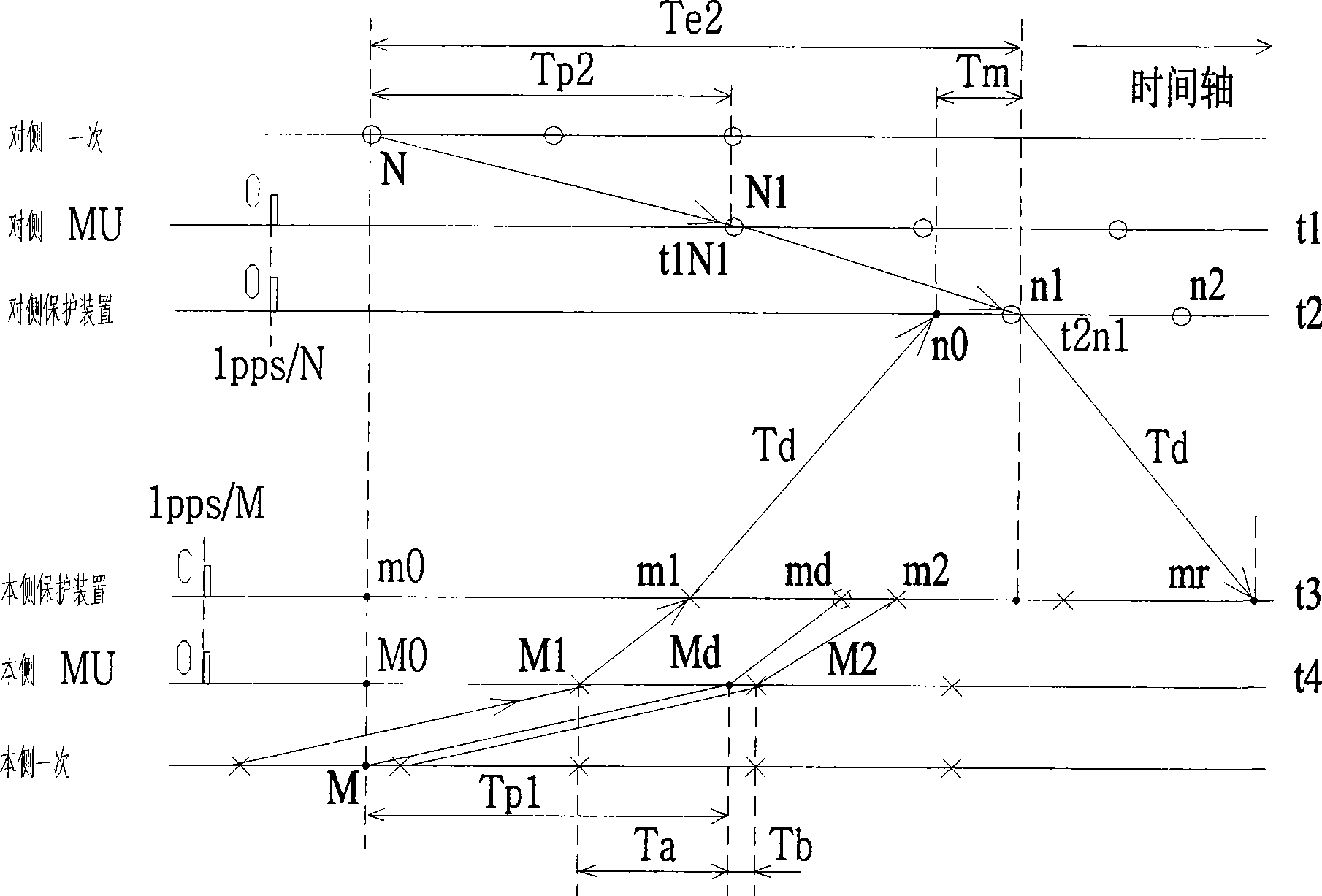
[0058] (1) There is an internal timer (clock) t3 in the processor of the protection device on the local side, and an internal timer t4 in the MU processor on the local side. The 1pps / M signal of the public clock source in the substation on the local side passes through the optical fiber port Connect to the protection device and MU at the same time;

[0059] (2) The processor of the protection device on this side receives the 1pps / M signal in the form of an external interrupt. If the 1pps / M signal appears, the processor will set t3 to 0 at the leading edge of the 1pps / M pulse, and then t3 will automatically count until the next 1pps / M When M appears, it is reset to 0, and this cycle repeats. The MU on this side also receives 1pps signal through external interrupt. If the 1pps / M signal appears, the processor will set t4 to 0 at the leading edge of the 1pps / M pulse, and then t4 will automatically count until the next Reset to 0 when 1pps / M appears once, and repeat like this;

[...


PUM


Abstract

The invention discloses a data synchronization method for a digitized fiber differential protection device. The method comprises the following steps that: (1) a protection device at each side and a merging unit are subjected to clock synchronization at respective side 1 pps; (2) the MU at each side is accessed to the protection device at respective side by an interface according with IEC61850-9 standard; (3) the protection device at each side calculates ET quadratic transformation time delay of sample data in each frame; (4) the protection device at each side calculates channel time delay Td; (5) the side sampling point time t4Md synchronous with an opposite side sampling point is calculated; and (6) each side device finds out two frames of data received before and after the t4Md time from the stored side MU sample data, a group of sampling values is acquired through interpolation calculation, and the group of sampling values is synchronous with the opposite side sample data of which sampling label is N1. The method can achieve data synchronization of the protection devices at two sides under the condition that the MU is accessed by the interface of the IEC61850-9 standard.

Description

technical field [0001] The invention relates to a data synchronization method of a digital optical fiber differential protection device, which belongs to the field of electric power system relay protection. Background technique [0002] With the gradual pilot and promotion of digital substation technology in the power system, various digital protection devices based on electronic transformer (ET) access have been gradually developed. Among these protection devices, the line optical fiber differential protection device is more complicated. One, because in addition to facing the common problems in the development of digital protection devices, it also needs to solve the problem of synchronizing the sampling data of the protection devices on both sides. Compared with traditional optical fiber differential protection devices, digital optical fiber differential protection has the following difficulties: [0003] (1) The electronic transformer and its merging unit (MU) manufactur...

Claims


Application Information

Patent Timeline
Patent Type & Authority Applications(China)
IPC IPC(8): H02H7/26H03L7/00
Inventor 曹团结陈建玉俞拙非黄国方
Owner NARI TECH CO LTD
Why Eureka
Try Eureka