Power conversion device and power generation conversion system

A power conversion device and power converter technology, applied in photovoltaic power generation, wind power generation, wind turbines, etc., to achieve the effect of improving operation continuity, improving voltage utilization rate, and preventing overvoltage

Active Publication Date: 2009-09-16
HITACHI LTD
View PDF1 Cites 17 Cited by
  • Summary
  • Abstract
  • Description
  • Claims
  • Application Information

AI Technical Summary

Problems solved by technology

The second method is to limit the upper limit value of the input current command value of the power converter for generating power contro

Method used


Image

  • Power conversion device and power generation conversion system
  • Power conversion device and power generation conversion system
  • Power conversion device and power generation conversion system

Examples


Example Embodiment

[0049] [Example 1]

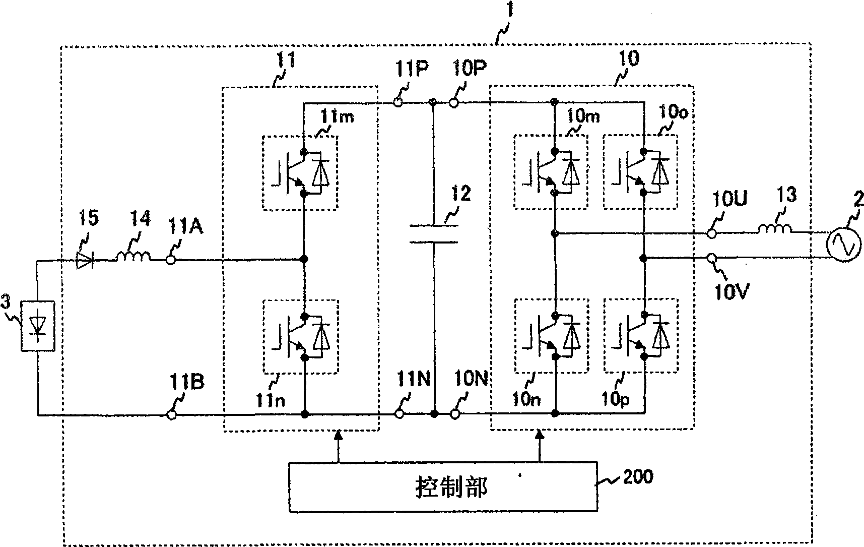
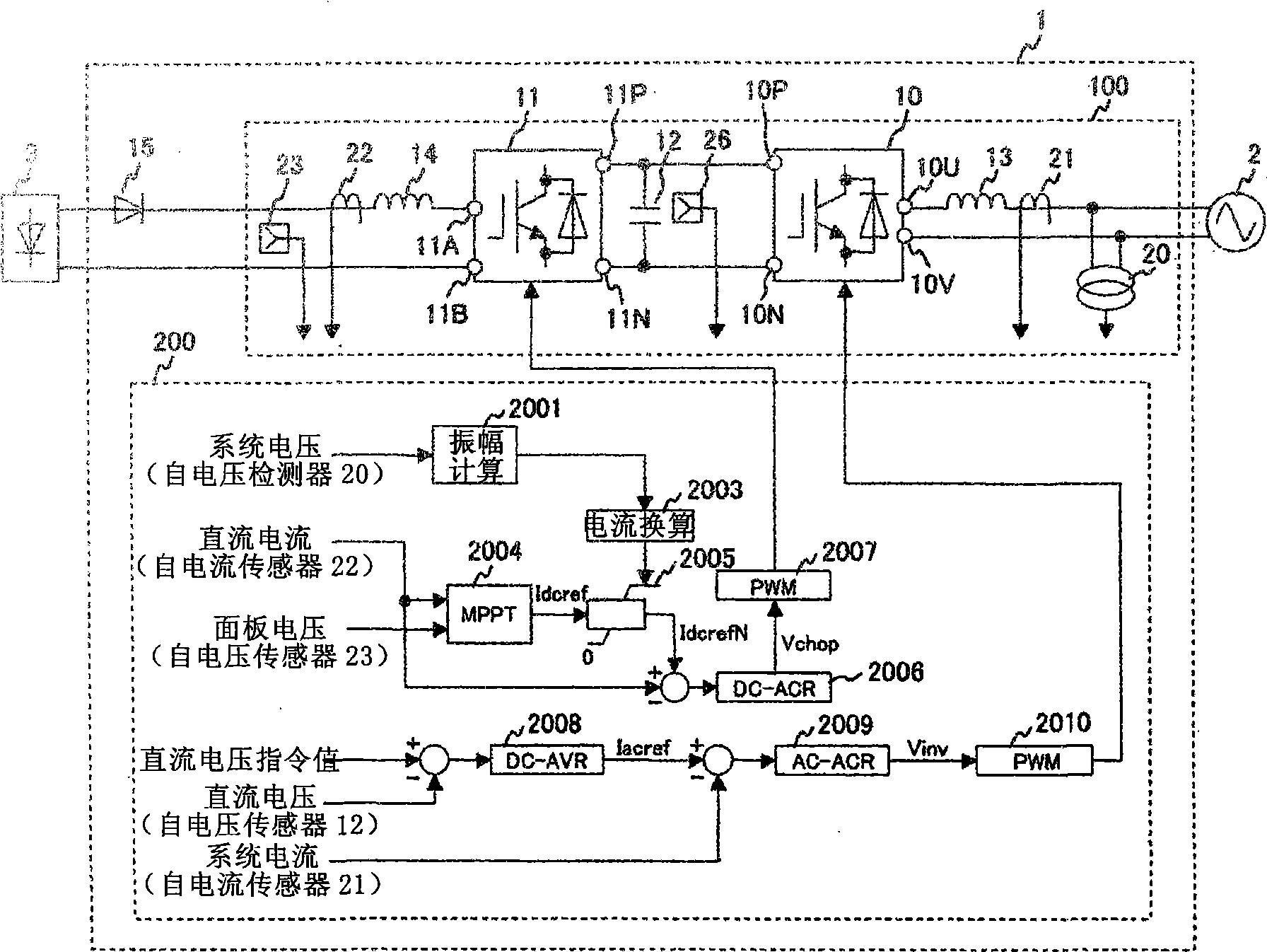
[0050] This embodiment is a power conversion device that is connected to a solar power generation panel and an AC system, converts the power generated by the solar power generation panel into AC power, and outputs it to the AC system.

[0051] That is, it includes: a power converter for generating power control, which controls the generated power from the solar panel, and converts the generated power into DC power; a smoothing capacitor connected to the output terminal of the power converter for generating power control; system interconnection A power converter connected to the power converter for power generation control and the smoothing capacitor, and converts the DC power into AC power and outputs it to the AC system; and a control unit that includes the voltage amplitude of the AC system as input and According to the voltage amplitude, the generated power limiting mechanism changes the upper limit value of the generated power of the power converter for po...

Example Embodiment

[0086] [Example 2]

[0087] Next, Example 2 of the present invention will be described. Figure 7 The main circuit structure of the power conversion device of the second embodiment is shown. In this embodiment, the same reference numerals are used to denote the same elements as in the first embodiment of the present invention, and the description is omitted.

[0088] This embodiment is characterized in that the AC system 2 is a three-phase AC system, and the power generation current limiting mechanism 2003 reduces the upper limit of the current command value limiter 2005 according to the positive phase voltage amplitude of the AC system.

[0089] The power converter 11 for power generation control of the power conversion device 1 of this embodiment is the same as that of the first embodiment. In addition, similar to the first embodiment, the power converter 11 for power generation control is connected to the photovoltaic power generation panel 3, and the power converter 30 for sys...

Example Embodiment

[0103] [Example 3]

[0104] Picture 11 The structure of the main part of the power conversion device of Example 3 is shown. In this embodiment, the same reference numerals are used to denote the same elements as in the first and second embodiments, and the description is omitted.

[0105] The power converter 30 for system interconnection of the power conversion device 1 is the same as in the second embodiment. In addition, the power converter 30 for system interconnection is connected to the AC system 2 and outputs power to the AC system 2 so that the terminal voltage of the smoothing capacitor 12 follows a predetermined voltage.

[0106] The difference from the first embodiment is that in the third embodiment, the power source connected to the power converter 11 for generating power control is a DC power source 5. In addition, with respect to the power conversion device of the second embodiment, the maximum power following operation of the photovoltaic power generation panel 3 ...


PUM


Abstract

The invention provides a power conversion device outputting the power generated by power source to the AC system and capable of improving the operation continuity of the AC system when the voltage decreasing. The power conversion device has an electric power converter (11) with one end connected to the AC system (2), the other end connected to the power source (3) for controlling the power generation of the generator; an electric power converter (10) for controlling the power outputted to the AC system; and a control portion (200) for controlling the electric power converter (10). An amplitude calculator (2001) calculates the voltage from the AC system, and executing current conversion to the voltage amplitude; an amplitude limiter (2005) limits the upper limit of power generated by the power source (3). A maximum power operation controller (20040 outputs the DC current and panel voltage and searches the current instruction value Idcref for executing maximum power operation. The current instruction value Idcref is limited between 0 to the upper limit, obtaining the different with IdcrefN DC current; the voltage instruction value Vchop is obtained by a current controller (2007) for outputting to the electric power converter (11).

Description

technical field [0001] The present invention relates to a power conversion device that converts the voltage and current of a power source and outputs power to an interconnected AC system. Background technique [0002] The introduction of distributed power systems such as photovoltaic power generation systems and wind power generation systems is being promoted all over the world. In a system where a large number of distributed power supply systems are connected, if the distributed power supply system is disconnected when the system voltage drops, the system voltage drop will further progress due to the power supply disappearing, and a large-scale blackout may occur. Therefore, it is desired that the distributed power supply can continue to generate electricity even when the system voltage drops. [0003] Most of these distributed power sources convert the power generated by the power source into DC power of a predetermined voltage through a power converter for power generati...

Claims


Application Information

Patent Timeline
IPC IPC(8): H02J3/38G05F1/67G05F1/66F03D9/00
CPCY02E10/58Y02E10/563Y02E10/56Y02E10/72Y02E10/76
Inventor 相原孝志伊藤智道宫田博昭谷口雅弘内山伦行小野濑贵之
Owner HITACHI LTD
Why Eureka
Try Eureka