
Magnetic suspension type motor base

A motor seat and magnetic levitation technology, applied in the direction of electromechanical devices, electrical components, electric components, etc., can solve the problems of increasing the friction loss of motor bearings, reducing the service life of the motor, heating, etc., to reduce the service life, reduce noise and vibration, simple effect

Inactive Publication Date: 2015-02-25
GUANGZHOU COLLEGE OF SOUTH CHINA UNIV OF TECH
View PDF5 Cites 0 Cited by
  • Summary
  • Abstract
  • Description
  • Claims
  • Application Information

AI Technical Summary

Problems solved by technology

[0002] Today's world has entered the era of electrification. More and more electrical equipment has motor parts, such as electric fans. Since the electric fan generates forward wind force, it will produce a backward reaction force on the main shaft of the electric fan. This reaction The force will act on the motor bearing, because the motor bearing is designed to withstand radial pressure instead of axial pressure, and the axial pressure generated by the reaction force will increase the friction loss of the motor bearing, resulting in serious heat generation, Generates noise and reduces motor life

Method used


Image

  • Magnetic suspension type motor base
  • Magnetic suspension type motor base
  • Magnetic suspension type motor base

Examples


Embodiment Construction

[0027] In order to further understand the present invention, the present invention will be described in detail below in conjunction with the accompanying drawings, but the protection scope of the present invention is not limited to the scope described in the embodiments.

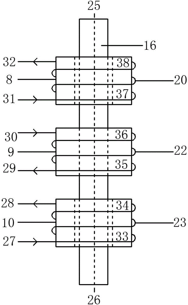
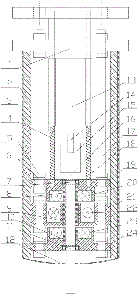
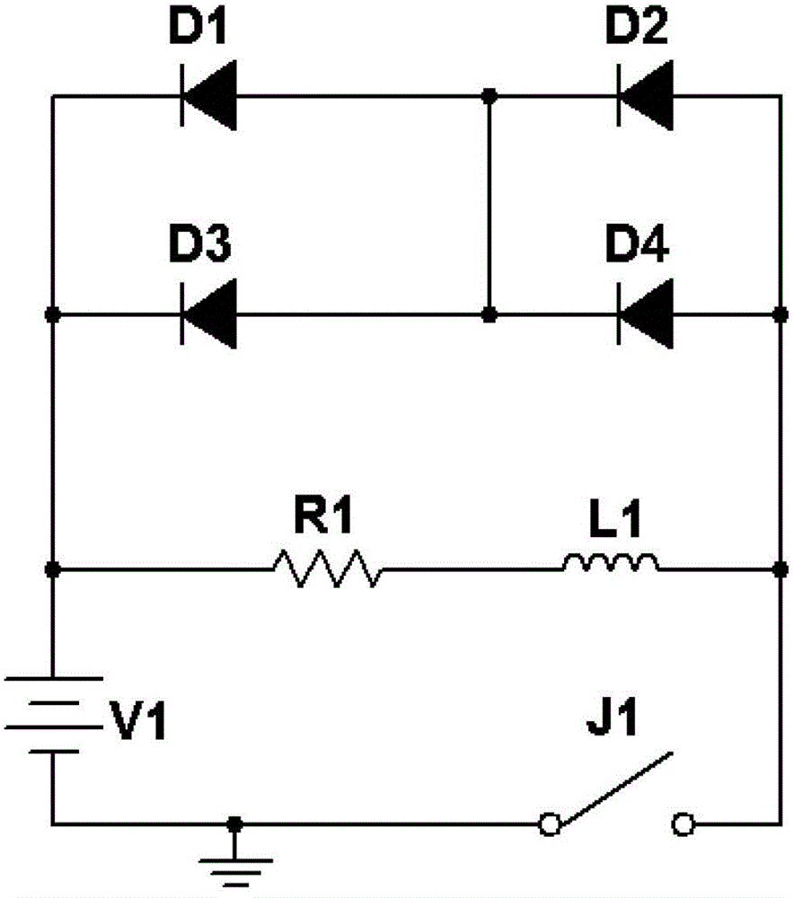
[0028] like Figure 1-3 As shown, a magnetic levitation motor seat mainly includes a transmission main shaft 16, an upper magnetic ring 8, a middle magnetic ring 9, a lower magnetic ring 10, an upper magnetic ring seat 19, a middle magnetic ring seat 21, a lower magnetic ring seat 24, a top seat 1. Prop 18, long screw shaft 17, upper auxiliary excitation coil 20, middle auxiliary excitation coil 22 and lower auxiliary excitation coil 23.

[0029] The drive shaft 16 is connected to the output shaft 14 of the motor 13 through a coupling 15; the upper magnetic ring 8, the middle magnetic ring 9, and the lower magnetic ring 10 are ring-shaped hollow magnets, and the upper magnetic ring 8 and the lower magnetic r...


PUM


Abstract

The invention discloses a magnetic suspension type motor base. A transmission main shaft of the motor base is in rigid connection with an output shaft of a motor through a coupling; an upper magnetic ring, a middle magnetic ring and a lower magnetic ring are circular hollow magnets; the transmission main shaft penetrates through central circular holes of the upper magnetic ring, the middle magnetic ring and the lower magnetic ring from top to bottom, wherein the transmission main shaft is tightly connected with the middle magnetic ring; the upper magnetic ring and the lower magnetic ring are movably connected with the transmission main shaft; gaps are reserved among the upper magnetic ring, the middle magnetic ring and the lower magnetic ring; the upper magnetic ring, the middle magnetic ring and the lower magnetic ring are fixed in an upper magnetic ring seat, a middle magnetic ring seat and a lower magnetic ring seat; an upper auxiliary excitation coil, a middle auxiliary excitation coil and a lower auxiliary excitation coil are arranged on the upper magnetic ring, the middle magnetic ring and the lower magnetic ring respectively; and the upper magnetic ring seat, the middle magnetic ring seat and the lower magnetic ring seat are fixed on a top seat through a plurality of long screws. By the magnetic suspension type motor base, counter-acting force can be transferred to the magnetic suspension type motor base by magnetic force, and axial force born by a motor bearing can be reduced or even eliminated.

Description

technical field [0001] The invention relates to a motor mount, in particular to a magnetic levitation motor mount. The magnetic levitation motor mount is suitable for electric fans, electric turbofans, ship electric drives, propeller propellers driven by internal combustion engines, etc., which can generate propulsion and provide power to motors. Where there is a reactionary force. Background technique [0002] Today's world has entered the era of electrification. More and more electrical equipment has motor parts, such as electric fans. Since the electric fan generates forward wind force, it will produce a backward reaction force on the main shaft of the electric fan. This reaction The force will act on the motor bearing, because the motor bearing is designed to withstand radial pressure instead of axial pressure, and the axial pressure generated by the reaction force will increase the friction loss of the motor bearing, resulting in serious heat generation, Generate noise...

Claims


Application Information

Patent Timeline
Patent Type & Authority Patents(China)
IPC IPC(8): H02K5/24
Inventor 张忠李彦豪马永良林立新
Owner GUANGZHOU COLLEGE OF SOUTH CHINA UNIV OF TECH
Learn More