Magnetic straight-moving driving rotation mechanism

A technology of magnetic force and linear motion, applied in the direction of electromechanical devices, electric components, electromechanical transmission devices, etc., can solve the problems of complex manufacturing, high cost, misuse of energy, etc. of the crankshaft, and achieve the effect of simple process, low cost and long life

Inactive Publication Date: 2009-09-16
刘新广
View PDF0 Cites 6 Cited by
  • Summary
  • Abstract
  • Description
  • Claims
  • Application Information

AI Technical Summary

Problems solved by technology

Therefore, the crank connecting rod mechanism is not only inefficient, but also causes some energy to be misused to damage the crankshaft, which is the fatal shortcoming of the crank connecting rod mechanism.
Furthermore, the crankshaft is complicated to manufacture and the cost is high

Method used


Image

  • Magnetic straight-moving driving rotation mechanism
  • Magnetic straight-moving driving rotation mechanism
  • Magnetic straight-moving driving rotation mechanism

Examples


Embodiment 1

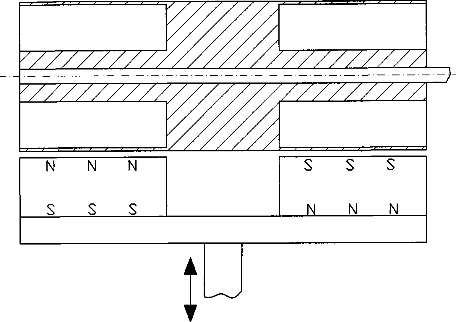
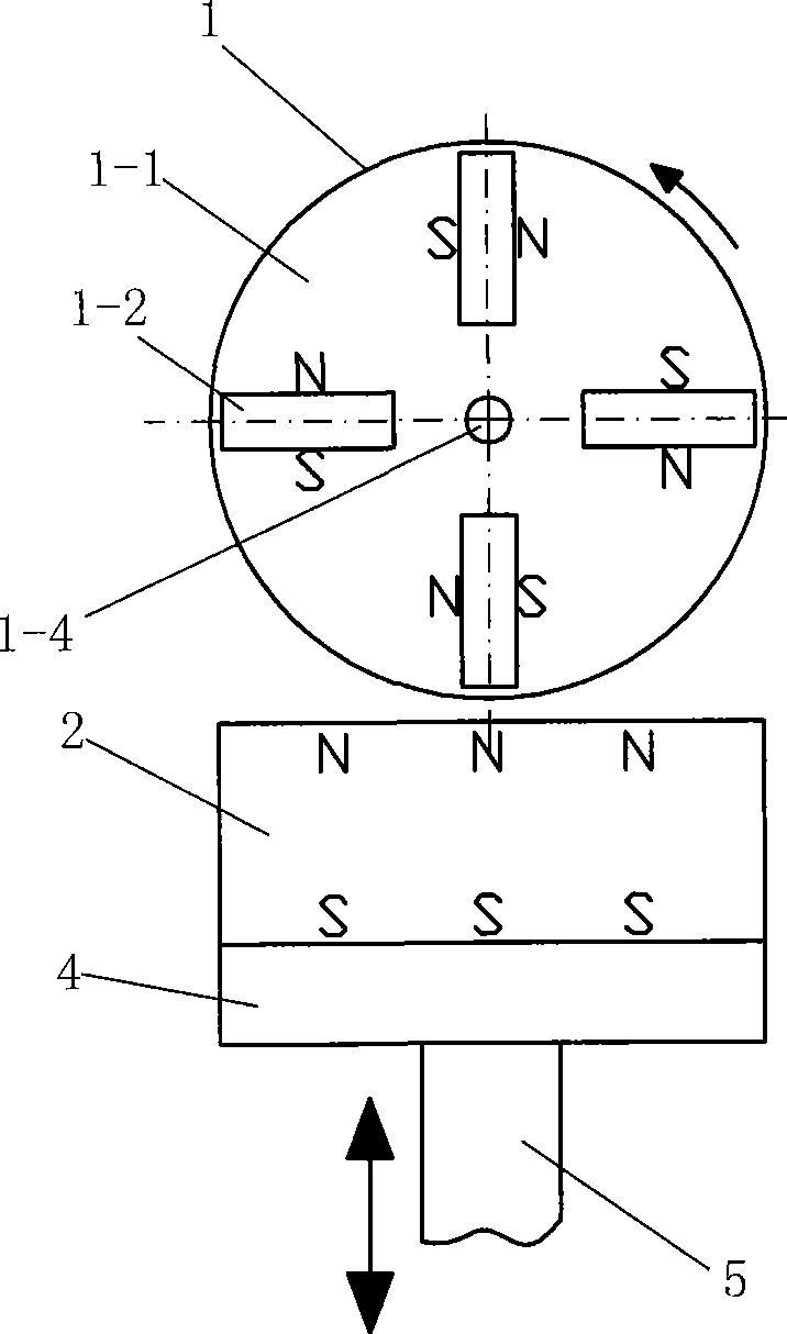
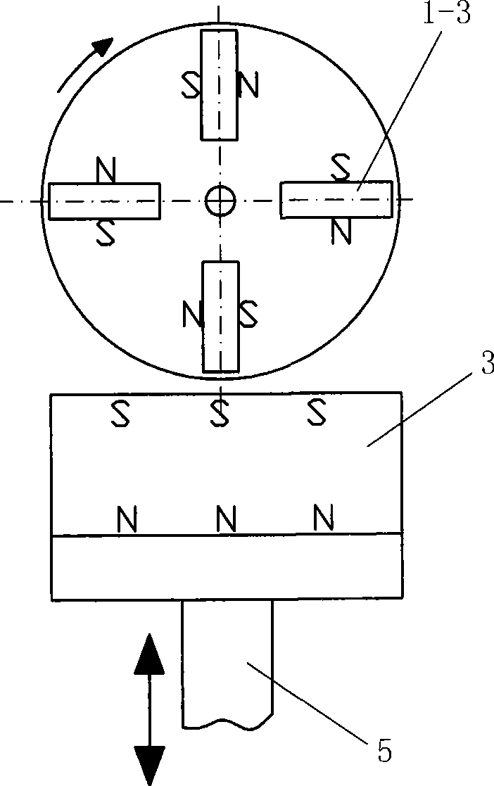
[0022] Embodiment one: if Figure 1 to Figure 3 Show. The magnetic wheel 1 is composed of several permanent magnetic plates 1-2, several permanent magnetic plates 1-3, and a non-magnetic cylinder 1-1 fixed on the rotating shaft 1-4. The permanent magnetic plates 1-2, permanent magnetic plates 1-3 are magnetized along the tangential direction (thickness direction), and the polarity of all permanent magnet plates 1-2 is clockwise (from figure 2 Look), the polarity order of all permanent magnet plates 1-3 is clockwise (from image 3 Look), the neutral plane of the permanent magnet plate 1-2 and the permanent magnet plate 1-3 passes the axis of the rotating shaft 1-4, and the rotating shaft 1-4 is installed on the frame (not drawing in the figure) with a bearing (not shown in the figure) On; the permanent magnet 2 and the permanent magnet 3 magnetized vertically are placed under the magnetic wheel 1, and the polarity direction on the permanent magnet 2 is opposite to that on the...

Embodiment 2

[0023] Embodiment two: if Figure 4 Show. A permanent magnet 7 magnetized vertically is placed below the magnetic wheel 6. The magnetic wheel 6 is the axial half of the magnetic wheel 1 in the first embodiment. The connecting rod 5 is fixed at the center of the bottom surface of the permanent magnet 7, and the connecting rod 5 is in addition One end is connected with a linear motion part (not shown in the figure).

Embodiment 3

[0024] Embodiment three: as Figure 5 Show. The two magnetic wheels 6 described in Embodiment 2 are placed on the upper and lower sides of the vertically magnetized permanent magnet 7, and the permanent magnet 7 is connected with a linear motion member (not shown) by a coupling.


PUM


Abstract

The invention provides a magnetic straight-moving driving rotation mechanism. A magnetic wheel consists of a plurality of permanent magnetic plates and a nonmagnetic cylinder that are fixedly connected on a rotation shaft; the permanent magnetic plates are respectively filled with the magnetism in the radial direction; all permanent magnetic plates have consistent polarity sorting directions; the neutral surface of the permanent magnetic plate passes by the axis line of the rotation shaft; the rotation shaft is arranged on the frame by a bearing; a permanent magnet filled with the magnetism in the vertical direction is arranged below the magnetic wheel; the bottom surface of the permanent magnet is fixed with a magnetic-conductive plate; the center of the bottom surface of the magnetic-conductive plate is fixedly connected with a connecting rod; and the other end of the connecting rod is connected with a linear movement part. The magnetic straight-moving driving rotation mechanism has no dead points, no friction, thus having the advantages of high efficiency, lubrication-free, energy-saving and environment-protection, long service life and low cost.

Description

technical field [0001] The invention relates to a mechanism for converting linear motion into rotation, in particular to a magnetic force direct drive mechanism, which belongs to mechanical technology. Background technique [0002] The existing linear and rotary motion conversion mechanism is a well-known crank-link mechanism, which is mainly composed of connecting rods, slide blocks (or pistons) and crankshafts. When the crank-link mechanism works, not only the friction force at the hinge is very large, but also when the slider moves along a straight line to the end of the stroke, the direction of movement of the connecting rod makes its long direction closer and closer to the direction of movement of the slider, and the connecting rod The driving torque to the crankshaft is getting smaller and smaller. When the slider moves to the end of the stroke, the driving torque of the connecting rod to the crankshaft is zero (called dead point), and a large bending destructive force...

Claims


Application Information

Patent Timeline
Patent Type & Authority Applications(China)
IPC IPC(8): H02K51/00
Inventor 刘新广
Owner 刘新广
Why Eureka
Try Eureka