Charge pump circuit

A charge pump and circuit technology, used in pump control, electrical components, output power conversion devices, etc., can solve problems such as overshoot and delay in charge pump circuits

Inactive Publication Date: 2009-09-16
SEIKO INSTR INC
View PDF2 Cites 9 Cited by
  • Summary
  • Abstract
  • Description
  • Claims
  • Application Information

AI Technical Summary

Problems solved by technology

[0008] However, since there is a parasitic capacitance or the like in the feedback system from the output terminal of the charge pump circuit to the oscillation circuit 20, a delay may occur in the feedback control and an overshoot may occur at the output terminal of the charge pump circuit.

Method used


Image

  • Charge pump circuit
  • Charge pump circuit
  • Charge pump circuit

Examples


Embodiment Construction

[0019] Hereinafter, embodiments of the present invention will be described with reference to the drawings.

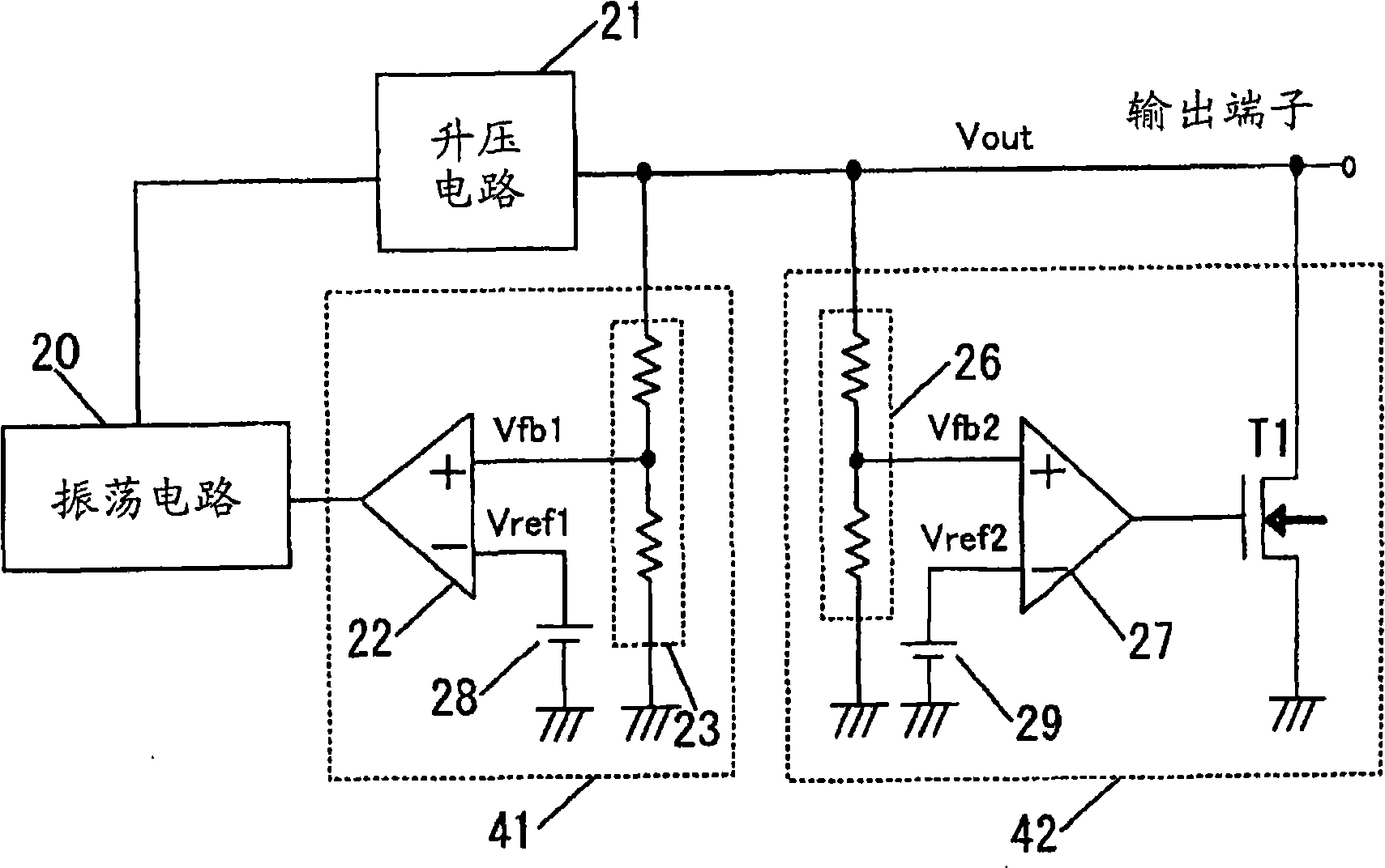
[0020] First, the configuration of the charge pump circuit will be described. figure 1 is a diagram showing a charge pump circuit.

[0021] The charge pump circuit has a voltage dividing circuit 23 , a reference voltage circuit 28 , a comparison circuit 22 , an oscillation circuit 20 and a voltage boosting circuit 21 . In addition, the charge pump circuit has a voltage dividing circuit 26, a reference voltage circuit 29, a comparison circuit 27, and a transistor T1.

[0022] The voltage dividing circuit 23 is provided between the output terminal of the charge pump circuit and the ground terminal. The reference voltage circuit 28 is provided between the inversion input terminal and the ground terminal of the comparison circuit 22 . The non-inverting input terminal of the comparison circuit 22 is connected to the output terminal of the voltage dividing circuit 23 , an...


PUM


Abstract

Provided is a charge pump circuit capable of shortening a settling time. When a boosted voltage (Vout) becomes high to be equal to or larger than an overshoot voltage, a transistor (T1) is turned on and an output terminal of the charge pump circuit is discharged. Accordingly, it is easy to reduce the boosted voltage (Vout) after an occurrence of an overshoot, and a period of time in which the boosted voltage (Vout) decreases from a voltage after the occurrence of the overshoot to a desired voltage is shortened, leading to a reduction in a settling time.

Description

technical field [0001] The present invention relates to charge pump circuits. Background technique [0002] The configuration of a conventional charge pump circuit will be described. Figure 5 is a diagram showing a conventional charge pump circuit. [0003] The charge pump circuit has a voltage dividing circuit 23 , a reference voltage circuit 28 , a comparison circuit 22 , an oscillation circuit 20 and a voltage boosting circuit 21 . [0004] Next, the operation of the conventional charge pump circuit will be described. [0005] The boosting circuit 21 performs a boosting operation based on the pump pulse output from the oscillation circuit 20, and outputs a boosted voltage Vout. The voltage dividing circuit 23 divides the boosted voltage Vout and outputs a divided voltage Vfb1. The reference voltage circuit 28 outputs a reference voltage Vref1. The comparison circuit 22 compares the divided voltage Vfb1 with the reference voltage Vref1 and operates (feedback control) ...

Claims


Application Information

Patent Timeline
Patent Type & Authority Applications(China)
IPC IPC(8): H02M3/07
CPCH02M1/32H02M2001/0045H02M3/073H02M1/0045F04B49/00F04B49/06
Inventor 川岛楠宇都宫文靖
Owner SEIKO INSTR INC
Why Eureka
Try Eureka