A sending method for reference signals
A reference signal and transmission method technology, applied in wireless communication, electrical components, network planning, etc., can solve problems such as poor cross-correlation, limited positioning performance, and affecting system transmission performance
- Summary
- Abstract
- Description
- Claims
- Application Information
AI Technical Summary
Problems solved by technology
Method used
Image
Examples
Embodiment 1
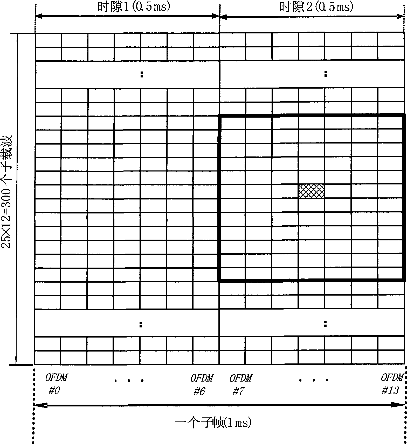
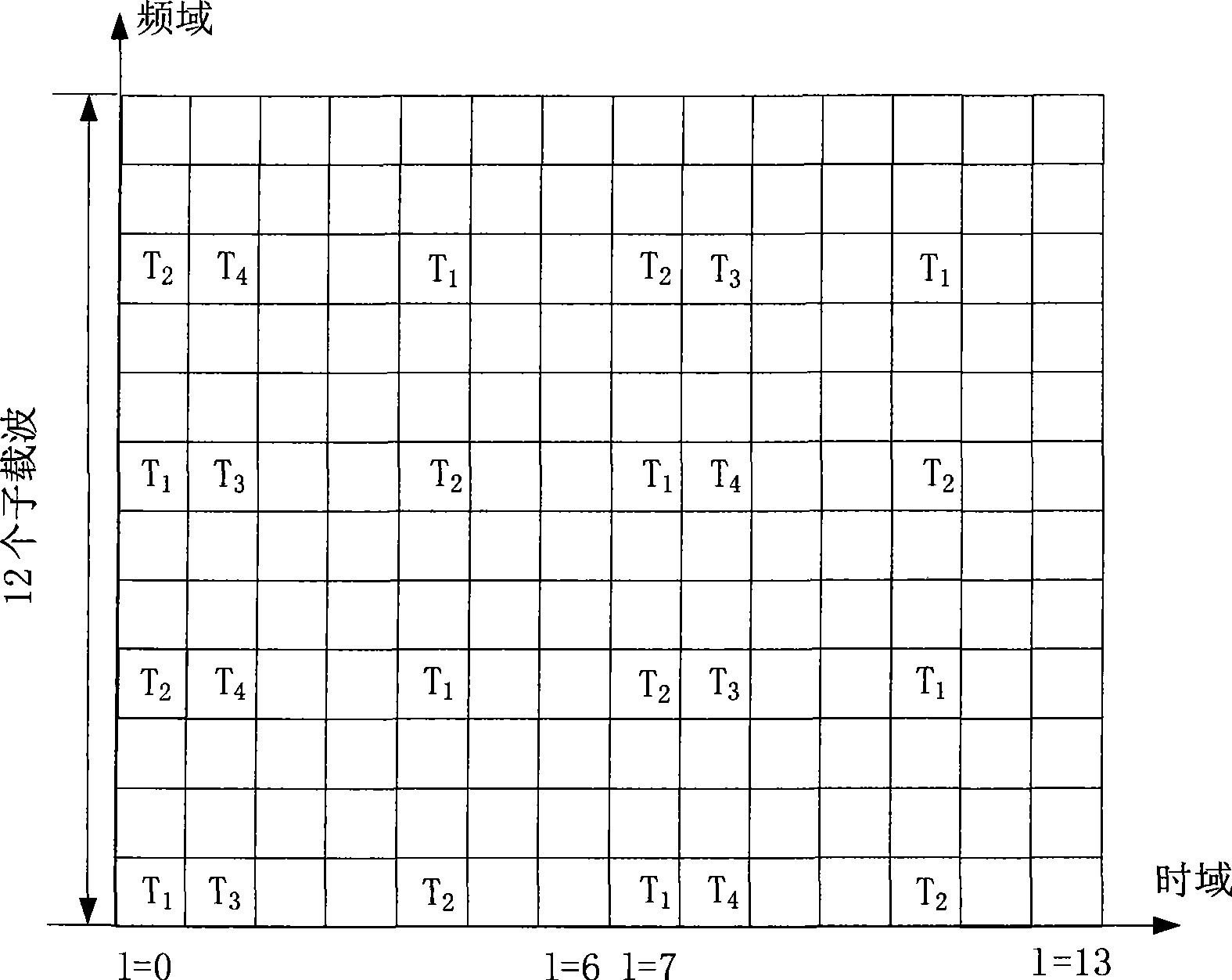
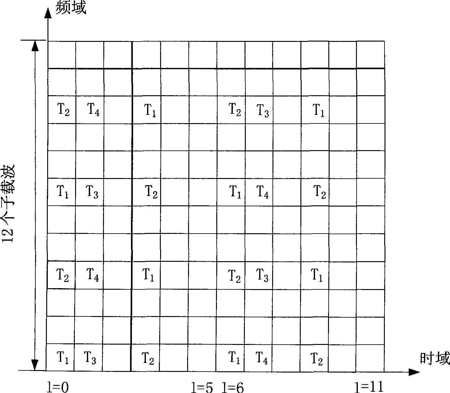
[0066] In Embodiment 1, in the time domain direction, the OFDM symbols used to send the reference signal in the resource block pair of the subframe are the OFDM symbols occupied by the physical downlink control channel and the common pilot in the resource block pair. All OFDM symbols except the OFDM symbol; in the frequency domain direction, only one subcarrier is occupied on each OFDM symbol used to send the reference signal to send the reference signal.
[0067] The number (indicated by n) and the position of the OFDM symbols used to send the reference signal are specifically determined as follows:
[0068] (1) For MBSFN subframes, the value of n is 10; the position of the OFDM symbol used to send the reference signal is the rest after removing the first two OFDM symbols (ie, the first and second OFDM symbols) in a resource block pair of OFDM symbols;
[0069] (2) For a non-MBSFN subframe using a conventional cyclic prefix, set the number of symbols for transmitting the phy...
Embodiment 2
[0102] In the second embodiment, the position of the OFDM symbol used to send the reference signal in the resource block pair in the time domain direction is the same as that in the first embodiment, but in the frequency domain direction, two OFDM symbols used to send the reference signal are required. subcarriers to send reference signals.
[0103] It is the same as the manner of determining the reference signal pattern in the first embodiment. After the array B is obtained, according to the number n of OFDM symbols for transmitting the reference signal in the subframe, n columns of the array B are selected to correspond one-to-one with the n OFDM symbols used to send the reference signal. In the domain direction, two subcarriers need to be used to send reference signals on each OFDM symbol used to send reference signals, then select n and the n orthogonal frequency division multiplexing symbols from the N elements of the array A One-to-one correspondence, the value of any e...
Embodiment 3
[0117] In embodiment three, the requirements for the number and position of OFDM symbols used for sending OFDM symbols in the time domain and the number of subcarriers occupied by each OFDM symbol in the frequency domain are the same as those in embodiment two. Embodiment three and embodiment two The difference is that the method of determining the position of the subcarrier used to send the reference signal on each OFDM symbol according to the obtained array B is different.
[0118] In the third embodiment, after the array B is obtained, according to the number n of OFDM symbols for transmitting the reference signal in the subframe, two different sets of n column values are selected in the array B for use with n OFDM symbols for transmitting the reference signal. For symbol correspondence, the positions of two subcarriers on n OFDM symbols used to send reference signals are determined, and the method for determining subcarriers is the same as that in Embodiment 2. The selec...
PUM
 Abstract
Description
Claims
Application Information
 - R&D
- Intellectual Property
- Life Sciences
- Materials
- Tech Scout
- Unparalleled Data Quality
- Higher Quality Content
- 60% Fewer Hallucinations
Browse by: Latest US Patents, China's latest patents, Technical Efficacy Thesaurus, Application Domain, Technology Topic, Popular Technical Reports.
© 2025 PatSnap. All rights reserved.Legal|Privacy policy|Modern Slavery Act Transparency Statement|Sitemap|About US| Contact US: help@patsnap.com


