
Grid structure

A grid structure, grid technology, applied in the direction of structural elements, wire fences, building components, etc., can solve the problems of firmly holding, weakening rods and wire strip materials, etc., and achieve the effect of simple manufacturing

Inactive Publication Date: 2009-09-16
约瑟夫·克里斯默
View PDF1 Cites 3 Cited by
  • Summary
  • Abstract
  • Description
  • Claims
  • Application Information

AI Technical Summary

Problems solved by technology

However, practice has shown that although the arrangement of the rods in substantially closed loops ensures a certain initial stability, the movement of the rings through the grid structure re-expands relatively quickly, so that the rods are no longer held firmly enough. In the loops of each zigzag wire strip
[0003] Practice has also shown that an additional fastening, for example by welding or installing holding clips, etc., means additional costs and thus additional costs during production on the one hand, and on the other hand through these supplementary connection measures, due to welding Heating may weaken rod and wire rod materials

Method used


Image

  • Grid structure
  • Grid structure
  • Grid structure

Examples


Embodiment Construction

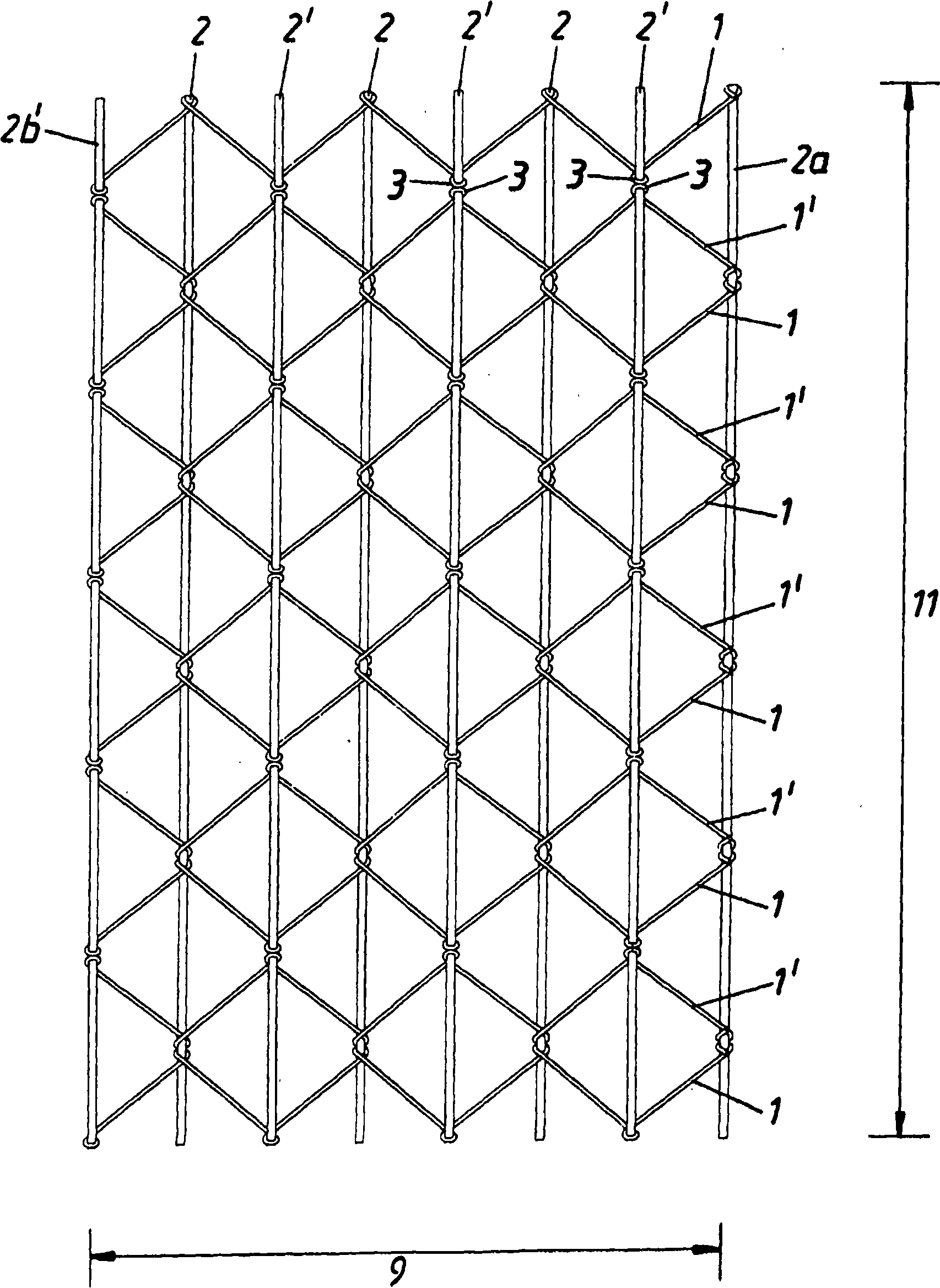
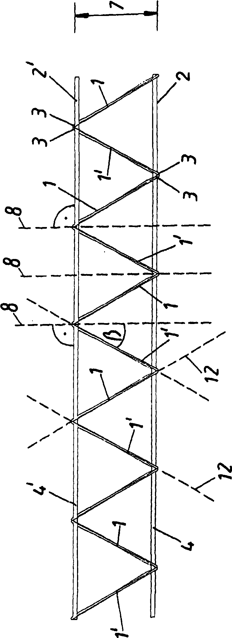
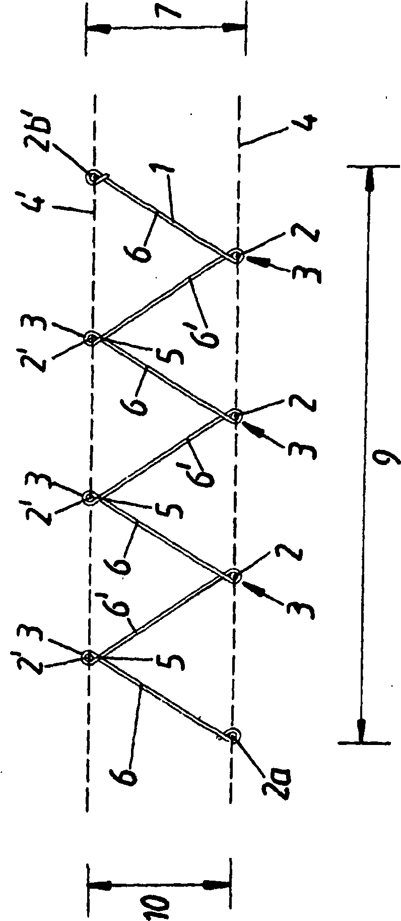
[0024] in press Figures 1 to 10 In the grid structure of , steel wire strips 1 , 1 ′ surround rods 2 , 2 ′ by means of loops 3 . The rods 2' are arranged in an upper plane 4'. The lower rods 2 are arranged in a lower plane 4 . The distance 7 between the planes 4 and 4' formed by the rods 2 and 2' is a multiple, preferably at least ten times, the largest diameter of the rods 2, 2'. This results in a three-dimensional structure which ensures very good stability or stabilization not only as a concrete reinforcement but also as a fixed grid. Two adjacent legs 6 and 6 ′ of the wire strip 1 intersect to form a loop 3 in the area of ​​intersection 5 . Here, the two legs 6 and 6' rest against each other or are only slightly spaced apart from each other. The smallest distance in the intersection region 5 is here less than three times the wire thickness, preferably less than the wire thickness. A substantially closed loop 3 is thereby formed. Therein, the rods 2 , 2 ′ are secured...


PUM


Abstract

Disclosed is a grid structure, especially of a reinforcement grid or floor mounting grid, comprising a plurality of wire paths (1, 1') which are arranged next to one another and are formed by wires that are bent in a zig-zag shape, and a plurality of particularly parallel bars (2, 2'). The wires of the wire paths (1, 1') embrace the bars (2, 2') in the form of substantially closed loops (3). The bars (2, 2') are clamped within the loops (3) of the wire paths (1, 1') in order to be fastened to the wire paths (1, 1'), the bars (2, 2') being twisted or tilted in relation to the loops (3) in at least one direction in order to be clamped within the loops (3) of the wire paths (1, 1').

Description

technical field [0001] The invention relates to a grating structure, in particular a steel grating or a floor-fixed grating, comprising a plurality of wire strips arranged side by side and a plurality of rods extending in particular parallel to each other, wherein the wire strips A steel wire is wound around each rod in a substantially closed loop. Background technique [0002] A grid structure of this type is known, for example, from GB 191501422. In this construction, the rods guided by the loops of the wire strips are substantially perpendicular to the planes formed by the meander-shaped wire strips. Although it is stated in this document that the structure itself, that is to say already before the filling, remains unchanged. However, practice has shown that although the arrangement of the rods in substantially closed loops ensures a certain initial stability, the movement of the rings through the grid structure re-expands relatively quickly, so that the rods are no lon...

Claims


Application Information

Patent Timeline
Patent Type & Authority Applications(China)
IPC IPC(8): B21F29/02E04C5/06
Inventor 约瑟夫·克里斯默
Owner 约瑟夫·克里斯默
Learn More