Tension device and heat exchange fin manufacturing machine

A technology of tensioning device and fins, which is applied in the direction of heat exchange equipment, feeding device, positioning device, etc., to achieve the effect of convenient adjustment

Inactive Publication Date: 2009-09-23
HIDAKA SEIKI KK
View PDF1 Cites 4 Cited by
  • Summary
  • Abstract
  • Description
  • Claims
  • Application Information

AI Technical Summary

Problems solved by technology

[0014] If the strip metal sheet 10 is overfeeded, the stamping unit 18 processes the wrong portion of the strip metal sheet 10, resulting in many inferior products

Method used


Image

  • Tension device and heat exchange fin manufacturing machine
  • Tension device and heat exchange fin manufacturing machine
  • Tension device and heat exchange fin manufacturing machine

Examples


Embodiment Construction

[0056] Preferred embodiments of the present invention will now be described in detail with reference to the accompanying drawings.

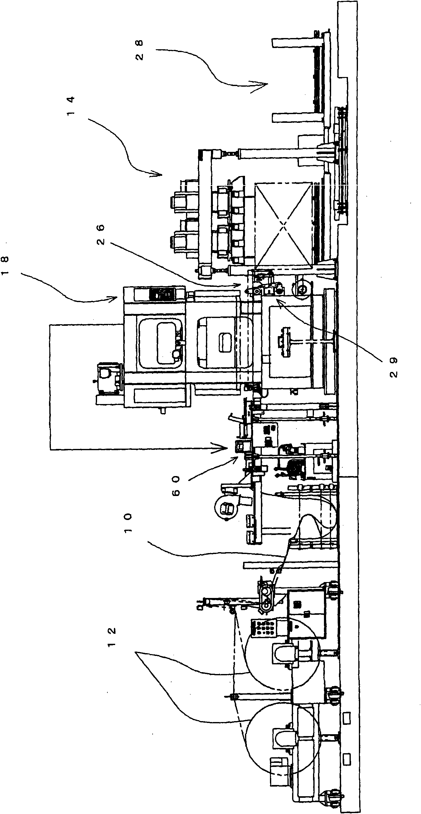
[0057] figure 1 An embodiment of the heat exchange fin manufacturing machine of the present invention is shown. In the heat exchange fin manufacturing machine, a strip-shaped thin metal plate 10 is extended from a coil 12 and fed to a punching unit 18 , and a regulated tension or the like is applied to the strip-shaped metal plate 10 . In the punching unit 18, a plurality of ringed through-holes are formed in the strip-shaped metal plate 10 by a pair of punching dies. Then, the band-shaped metal plate 10 is cut with the cutter 26 of the punching unit 18 to form a plurality of elongated fin pieces having a prescribed width. The elongated fin members are fed sequentially to the air suction unit 14 . When feeding the elongated fin member to the suction unit 14 with a prescribed length, the cutter of the punching unit 18 cuts the elongated fin me...


PUM


Abstract

The tension device comprises: a feeding unit for feeding a band-shaped metal plate to a press unit; and a holding unit for applying tension to the band-shaped metal plate. The feeding unit is constituted by a moving member and a feeding pin. The front end of the feeding pin has a slope face so as to engage with a collared through-hole of the band-shaped metal plate when the moving member moves in a feeding direction of the band-shaped metal plate and so as to disengage therefrom when the moving member stops and moves in the reverse direction. The holding unit has a holding member, which holds and applies prescribed tension to the band-shaped metal plate when the moving member stops and which releases the band-shaped metal plate when the moving member starts to move in the feeding direction.

Description

technical field [0001] The present invention relates to a tensioning device and a heat exchange fin manufacturing machine, and more particularly to a tensioning device comprising a feeding unit and a holding unit for intermittently feeding a band-shaped metal plate to a punching unit to form a belt loop through hole thereon, and a holding unit for applying tension to a portion of the strip-shaped metal sheet between the feeding unit and the holding unit when the punching unit stops feeding the strip-shaped metal sheet to the punching unit, the present The invention also relates to a heat exchange fin manufacturing machine with a tensioning device. Background technique [0002] Heat exchange fins used in air conditioners etc. by e.g. Figure 6 Shown heat exchange fin manufacturing machine to manufacture. The heat exchange fins are formed by processing a band-shaped metal plate 10 made of, for example, aluminum. A strip of metal sheet 10 extends from a roll 12 . A strip-sha...

Claims


Application Information

Patent Timeline
Patent Type & Authority Applications(China)
IPC IPC(8): B21D43/04B21D28/26B21D43/20B65H23/04B65H20/00
CPCB21D43/06B65H2701/173B21D43/11B65H20/22B21D43/00B21D53/04B30B15/30
Inventor 远藤将司岩崎诚
Owner HIDAKA SEIKI KK
Why Eureka
Try Eureka