
Visual system for ball picking robot in stadium

A technology of robot vision and robot, which is applied in the field of vision system, can solve problems such as large amount of calculation, singleness, inability to complete recognition and planning, etc., and achieve the effect of fast processing speed

Inactive Publication Date: 2009-09-23
BEIJING INSTITUTE OF TECHNOLOGYGY
View PDF0 Cites 49 Cited by
  • Summary
  • Abstract
  • Description
  • Claims
  • Application Information

AI Technical Summary

Problems solved by technology

[0004] When cleaning balls in the stadium, using the existing robot vision system and machine vision recognition technology cannot meet the needs of the robot when picking up the ball, which is mainly caused by the following reasons:
[0005] 1. When completing the work of picking up balls, the robot needs to recognize many balls at the same time. There are many disturbances in the recognition process, such as light changes, other non-ball objects, and people moving in the field. Only relying on a single color recognition cannot complete the recognition Task
[0006] 2. Since the image collected by the centralized global camera is directly used for global calculation, this method has a large amount of calculation and poor real-time performance
[0007] 3. In the process of picking up balls by the robot, due to the large number of balls and irregular distribution, the movement path of the robot should be reasonably planned when picking up the balls. However, the existing vision system, such as the vision system of robot football, Then the path planning in the multi-sphere environment cannot be completed
[0008] 4. When multi-robots complete the work of picking up balls in a multi-ball environment, using existing systems and technologies, it is impossible to complete the identification and planning tasks

Method used


Image

  • Visual system for ball picking robot in stadium
  • Visual system for ball picking robot in stadium
  • Visual system for ball picking robot in stadium

Examples


Embodiment Construction

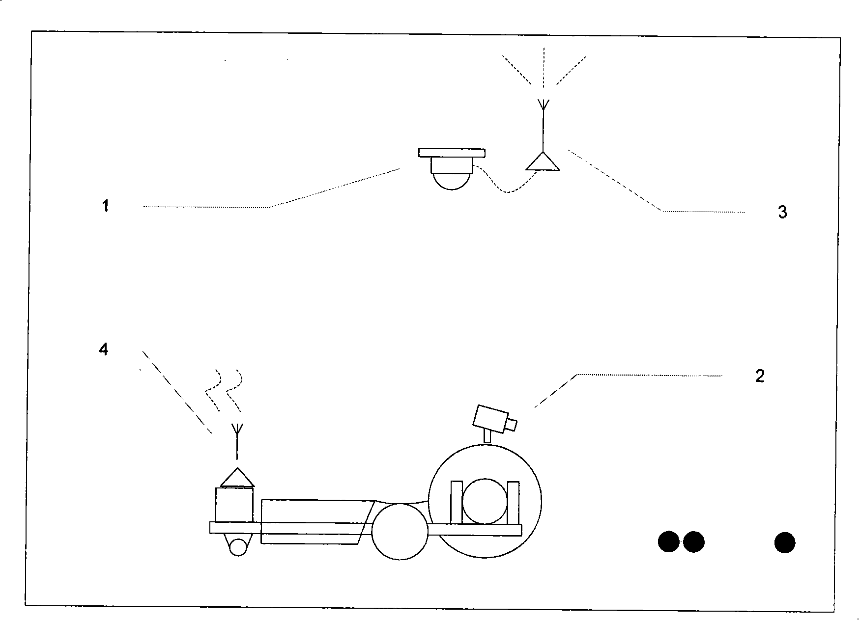
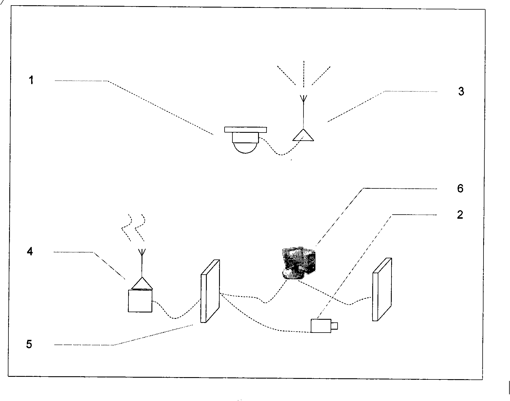
[0032] The vision system of the stadium ball picking robot of the present invention comprises a global camera (1), a robot carrier camera (2), wireless video transmission modules (3), (4), an image acquisition card (5) and an image processor (6). The global camera (1) uses the analog interface camera (1). The global camera (1) is installed above the field, and it is guaranteed to be able to fully photograph the sports field. The wireless video transmission modules (3), (4) adopt analog signal wireless video transmission modules (3), (4). The analog output end of the global camera (1) is connected with the transmitting end (3) of the wireless video transmission module through an AV video cable. The output end of the wireless video transmission receiver (4) is connected with the input end of the image acquisition card (5), the image acquisition card (5) is installed on the image processor (6), and the image processor (6) is installed inside the robot, Simultaneously, the image...


PUM


Abstract

The invention relates to a visual system for a ball picking robot in a stadium, which comprises a global camera, a robot carrier camera, a wireless video transmission module, an image acquisition card and an image processor. The image acquisition card is used for transmitting video signals acquired by the global camera and the robot carrier camera to the image processor; and the image processor is used for processing the video signals according to visual signals and transmitting corresponding commands to the robot. The image processor is used for identifying a ball and the robot by utilizing the color and the shape, judging the relative position of the ball and the robot in real time, and then carrying out route planning to the robot according to position information provided according to an identification algorithm so that the robot can finish the ball picking task through selecting an optimal route. The invention can control the robot to finish the ball picking task under the multi-ball environment, has quick processing speed and is suitable for various stadium environments.

Description

technical field [0001] The invention relates to a vision system of a ball picking robot in a stadium. Background technique [0002] With the improvement of living standards, people's fitness needs are becoming more and more intense. Going to the stadium for various ball games has become the first choice for people. When carrying out various ball games, such as table tennis and tennis, picking up balls becomes an extremely time-consuming work. At present, stadium ball cleaning equipment still needs to be operated by people. These simple and repetitive tasks consume a lot of human resources. Therefore, a vision system that can provide environment positioning, perception and path planning for the stadium ball picking robot is needed to solve the above problems. [0003] The robot vision system can adopt a centralized global camera, which can obtain the global information in the robot motion scene, and facilitate the global positioning of the robot. Most of the existing robo...

Claims


Application Information

Patent Timeline
IPC IPC(8): B25J9/16B25J19/04A63B69/00G06K9/00
Inventor 付梦印杨毅刘明阳付元雷金周熊之涛赵诚王在华朱昊
Owner BEIJING INSTITUTE OF TECHNOLOGYGY
Learn More