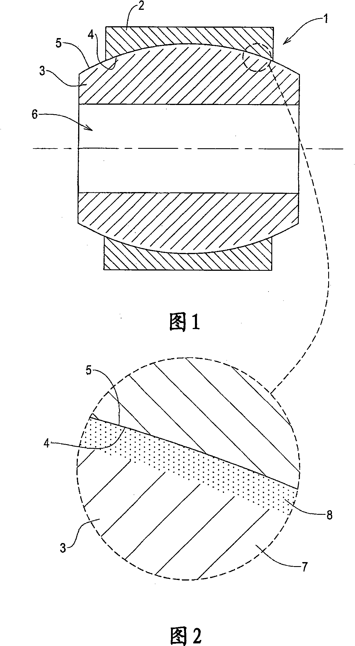
An aerospace bearing component
A technology of bearings and components, applied in the direction of bearing components, rigid supports of bearing components, shafts and bearings, which can solve problems such as limiting pressure
- Summary
- Abstract
- Description
- Claims
- Application Information
AI Technical Summary
Problems solved by technology
Method used
Image
Examples
Embodiment 1
[0088] Example 1: TPO using a constant oxygen flow: the effect of temperature on the process
[0089] The implemented three-pole plasma oxidation process (TPO) is to perform 240 minutes on the Ti-6Al-4V test plate (purchased from Titanium International, UK) at three different temperatures (600℃, 650℃ and 700℃) Hardening. During the ongoing process, the oxygen flow remains constant. Ti-6Al-4V test disc in annealed state (384±20HK 0.1 The thickness under) is 3mm, the diameter is 30mm, and after ultrasonic cleaning in alkaline solution, it is polished to a surface roughness of Ra=0.040±0.007μm, and then placed in the processing chamber (purchased from Tecvac Limited) IP 70 chamber).
[0090] Reducing the final pressure to less than 5×10 -3 After Pa, argon gas is introduced into the above-mentioned chamber to make the pressure reach 2.0 Pa for the splash cleaning step. A bias voltage of -1000V was applied to the above-mentioned workpiece (test disc), and splash cleaning was performe...
Embodiment 2
[0101] Example 2: TPO using pulsed oxygen flow to heat the plasma in an inert gas, or Inert gas and nitrogen heat to suppress the top oxide layer
[0102] In order to show the effect of this pulse / plasma heating condition, the surface hardness after annealing is 384±20HK 0.1 The Ti-6Al-4V test disc with surface roughness Ra=0.040±0.007μm was tested in four rounds at 700℃. The parameters of each round of test discharge (bias voltage and current density of the workpiece and resistance wire) are set to be the same as in Example 1 (respectively -200V, -200V and 1.5mA / cm 2 ). The total pressure in the TPO process is 0.4 Pa, and the partial pressures of argon and oxygen are 0.28 and 0.12 Pa, respectively. As explained in Example 1, before pulse TPO, splash cleaning and plasma heating were also performed. The oxygen flow in this embodiment is not kept constant during the entire treatment process, but is periodically pulsed, but the argon flow remains constant. The duration of this pu...
Embodiment 3
[0110] Example 3: Coating with three-pole plasma oxidation followed by spraying
[0111] As explained in Example 2, the emission of pulsed TPO followed by a plasma heating step in an inert gas or inert gas and nitrogen can produce several TPO layers with oxygen diffusion zones without any top Oxide layer. If the object is to be covered with several types of PVD or CVD films (for example, nitrides, carbides and carbonitrides), this structure is likely to be required, because when this type of film is attached to the oxidized When it is on the substrate (that is, there is a very thin oxide layer on their surface), it limits the adhesion of the coating.
[0112] To illustrate the advantages of TPO and sputtering, four pulse TPO treatments were performed on several samples of Ti-6Al-4V coated with PVD TiN with a thickness of 1.6μm, and then as described in Example 2. Plasma heating was performed at 700°C for a total time of 240 minutes. This treatment is realized in a two-cycle proce...
PUM
| Property | Measurement | Unit |
|---|---|---|
| depth | aaaaa | aaaaa |
| depth | aaaaa | aaaaa |
| depth | aaaaa | aaaaa |
Abstract
Description
Claims
Application Information
 - R&D
- Intellectual Property
- Life Sciences
- Materials
- Tech Scout
- Unparalleled Data Quality
- Higher Quality Content
- 60% Fewer Hallucinations
Browse by: Latest US Patents, China's latest patents, Technical Efficacy Thesaurus, Application Domain, Technology Topic, Popular Technical Reports.
© 2025 PatSnap. All rights reserved.Legal|Privacy policy|Modern Slavery Act Transparency Statement|Sitemap|About US| Contact US: help@patsnap.com


