Movable transition track bridge for heating furnace

A transitional track, movable technology, used in lighting and heating equipment, furnaces, furnace components, etc., can solve the problem of inability to meet the use of large-scale equipment and technological development, occupying space and shortening the length of the entire machine train, furnace sealing and poor insulation effect, etc. problems, to achieve the effect of significant economic and social effects, compact structure and novel structure

Inactive Publication Date: 2009-09-23
SUZHOU LONGRAY THERMAL TECH
View PDF2 Cites 2 Cited by
  • Summary
  • Abstract
  • Description
  • Claims
  • Application Information

AI Technical Summary

Problems solved by technology

In order to reduce the friction between the material pad and the track when pushing the ingot, the surface of the track is equipped with a lubricating oil filling hole. When using it, a special lubricating pump is used to automatically add oil. After the lubricating pump is started, the oil is sprayed onto the track surface. The lubricating oil is brought into the furnace when the pad belt ingot is pushed into the furnace. Since the fixed installation of the track occupies a certain space, the furnace door, as one of the key components of the furnace, is more difficult to design, and the furnace door structure needs to be processed The gap is opened and the local thickness is thinned. It is not effective for wide furnace doors, and the furnace sealing and heat insulation effects are poor.
[0004] Therefore, under the existing technical conditions, the disadvantages of using the fixed transition track are: ① For the matching use of the wide furnace door, the deformation of the furnace door and the leakage of the furnace door are serious, and the existing equipment forms cannot meet the use of large equipment and Technological development, and it does not conform to the national energy conservation and emission reduction policy; ②The form of the transitional track bridge determines the configuration of mechanical equipment outside the furnace, reducing the space occupied by it can shorten the length of the entire machine train and reduce the investment cost of the machine train

Method used


Image

  • Movable transition track bridge for heating furnace
  • Movable transition track bridge for heating furnace
  • Movable transition track bridge for heating furnace

Examples


Embodiment Construction

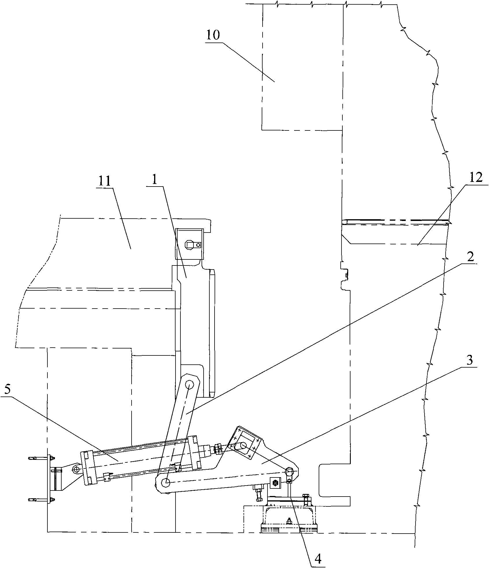
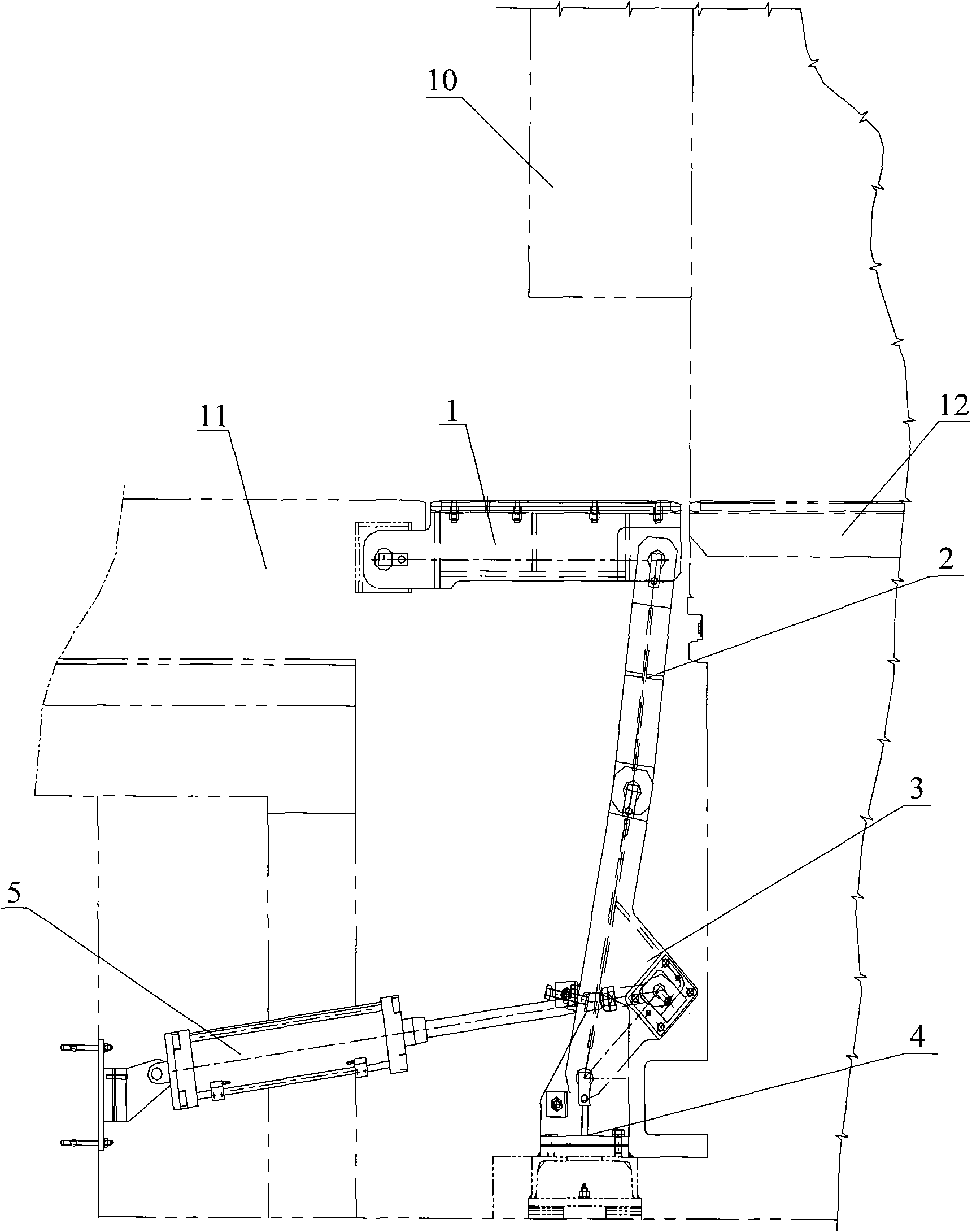
[0021] The track bridge is a transitional part used in the process of moving the ingot from the inside of the heating furnace to the track outside the furnace or from the outside of the furnace to the track inside the furnace. The reliability and characteristics of its performance determine the mechanization level of the heating furnace equipment and the characteristics of the furnace door. The movable track bridge of the present invention is a movable structural member similar to the movable knee joint of a human body, and is assembled from a plurality of detachable and movable parts, and its action is driven by a cylinder. When the furnace needs to feed or discharge materials, the cylinder piston rod is stretched out to push the crank and the track out from the vertical state to the horizontal state. When the feed or discharge action is completed, the cylinder piston rod retracts and returns to its original position.

[0022] figure 1 and figure 2 As shown, the movable tra...


PUM


Abstract

The invention provides a movable transition track bridge for a heating furnace, which comprises a track, a connecting rod, a crank and a cylinder, wherein a fixed end of the track is hinged with a track outside the furnace, a movable end of the track is hinged with one end of the connecting rod, the other end of the connecting rod is hinged with a movable end of the crank, a fixed end of the crank is hinged with a support, and the track, the connecting rod and the crank form a crank and rocker mechanism; and the cylinder is arranged on a foundation outside the furnace, a piston rod of the cylinder is hinged with the crank, the cylinder provides a power source for the crank and rocker mechanism, the piston rod of the cylinder drives the crank to rotate, and the track rotates along a path of a one fourth circle under the staged driving of the crank and the connecting rod to ensure the conversion of the track from a vertical state to a horizontal state. The movable transition track bridge satisfactorily ensures the integrity and good sealing of a furnace door structure, reduces the fault rate of a furnace door of the heating furnace, and realizes the interlocking and automatic control of various positions of equipment.

Description

technical field [0001] The invention relates to a movable track bridge, in particular to a track bridge for a movable transition of a propulsion heating furnace. Background technique [0002] The use of a new type of high-efficiency and energy-saving heating furnace as the heat treatment equipment of the hot rolling production line is a necessary condition for realizing high production capacity, low energy consumption and ensuring product quality in hot rolling production. During the propulsion process of the ingot from the processing equipment outside the furnace to the track in the furnace, or the retrieving process from the track in the furnace to the equipment outside the furnace, the main measure to increase the smooth operation of the ingot is to use a fixed transition track to fill The gap between the track outside the furnace and the track inside the furnace makes the ingot stable and reliable when it is pushed horizontally. [0003] A fixed transition track is used...

Claims


Application Information

Patent Timeline
Patent Type & Authority Applications(China)
IPC IPC(8): F27D3/02
Inventor 陈景阁闫辉杨光勇贵广臣
Owner SUZHOU LONGRAY THERMAL TECH
Why Eureka
Try Eureka