Method for analyzing vortex vibration and fatigue of depth tension-type vertical pipe

A vortex-induced vibration and fatigue analysis technology, which is used in the testing of mechanical components, the testing of machine/structural components, and measuring devices. casing stress and other issues to achieve the effect of improving accuracy

Inactive Publication Date: 2009-09-23
OCEAN UNIV OF CHINA
View PDF0 Cites 44 Cited by
  • Summary
  • Abstract
  • Description
  • Claims
  • Application Information

AI Technical Summary

Problems solved by technology

[0022] 1. The vibration response in the downstream direction is not considered, so the displacement response and stress response are small, and the calculation results are unsafe
[0023] 2. The lateral flow response calculated by the wake oscillator model has a large error, mainly because the wake oscillator model regards the fluid in the wake as vibrating in the same mode as an object with the same nature (with a fixed shape) as the solid. and interact with the structure
[0024] 3. The vortex-induced lift model does not consider the fluid-solid coupling effect, so it is only suitable for VIV analysis in the locked area
[0025] 4. The frequency of the vortex-induced lift force adopts the Strouhal frequency, but in the locked area, the vortex discharge frequency does not conform to the Strouhal frequency calculation formula
However, the existing software uses a single-layer pipe model with equivalent bending stiffness, which results in a smaller calculated value of the axial inner wall bending stress (deviation of inner diameter), a larger calculated value of tensile stress (deviation of cross-sectional area), and a lower calculated value of hoop stress. Small (wall thickness deviation), the radial stress calculation value is too large (the stress situation does not match the actual situation)
[0027] 6. The stress of oil pipe and inner casing cannot be calculated, so the strength and fatigue life of oil pipe and inner casing cannot be checked

Method used


Image

  • Method for analyzing vortex vibration and fatigue of depth tension-type vertical pipe
  • Method for analyzing vortex vibration and fatigue of depth tension-type vertical pipe
  • Method for analyzing vortex vibration and fatigue of depth tension-type vertical pipe

Examples


Embodiment Construction

[0051] The present invention will be further described in detail below with reference to the accompanying drawings.

[0052] The purpose of this invention is to:

[0053] 1. In the VIV analysis of the deepwater riser, the downstream vibration is considered, so that the analysis model and results are more consistent with the actual engineering problems.

[0054] 2. Improve the existing vortex-induced lift model, consider the influence of the fluid-structure interaction effect on the vortex-induced lift, and improve the VIV analysis accuracy.

[0055] 3. Improve the calculation model of the existing vortex discharge frequency so that it is not only applicable to the locked area, but also to the non-locked area.

[0056]4. Using the time domain analysis method, the maximum amplitude of the riser VIV and its stress and fatigue damage can be analyzed intuitively.

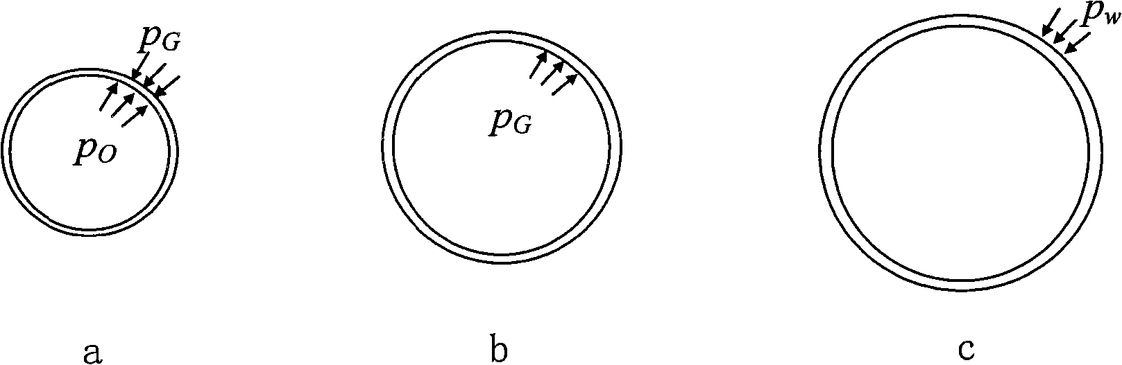
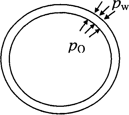
[0057] 5. Calculate the stress by using the actual structure of the riser (tube-in-tube), so that the calculation of...


PUM


Abstract

A method for analyzing vortex vibration and fatigue of a depth tension-type vertical pipe, which relates to the field of depth vertical pipe design, comprises the following specific steps of: step 1. obtaining flow field data; step 2. substituting the flow field data into vertical pipe vibration equations 6 and 7; step 3. solving the equations 6 and 7 by using a finite element method, and obtaining calculation results including displacement, velocity, accelerated velocity and stress time interval; and step 4. counting stress cycle number n(i) of an amplitude within a certain time by adopting a rain-flow counting method according to the calculation results, and substituting the n(i) into a fatigue damage calculation formula 8 to calculate the fatigue damage. The method for analyzing vortex vibration and fatigue of the depth tension-type vertical pipe improves the accuracy of stress calculation by adopting a practical pipe-in-pipe model and simultaneously considering direct flow vibration and cross flow vibration.

Description

technical field [0001] The invention relates to the field of deep-water riser design, in particular to a method for vortex-induced vibration and fatigue analysis of a deep-water top-tensioned riser. Background technique [0002] VIV is a peculiar vibration phenomenon of a cylinder under the action of a steady flow. Specifically, VIV is a cylinder vibration phenomenon caused by vortex shedding, and is a vibration caused by the alternating vortex discharge at the wake of the cylinder. For rigid cylinders and cylinders with less flexibility (general engineering structures), the amplitude perpendicular to the direction of flow velocity (cross-flow direction) is much larger than that parallel to the direction of flow velocity (forward-flow direction), and the vibration frequency is the direction of flow velocity half the vibration frequency. Therefore, in the existing VIV research, the forward-flow vibration is generally ignored, and only the cross-flow vibration is studied. Th...

Claims


Application Information

Patent Timeline
Patent Type & Authority Applications(China)
IPC IPC(8): G01M13/00
Inventor 黄维平唐世振上官丽红于卫红
Owner OCEAN UNIV OF CHINA
Why Eureka
Try Eureka