Coupled cavity for gyro-traveling wave amplifiers and coupling mode therefor

A traveling wave amplifier, coupled cavity technology, applied in waveguide devices, electrical components, connecting devices, etc., can solve problems such as limiting the research and development and application scope of millimeter-wave high-power devices

Inactive Publication Date: 2009-09-23
INST OF ELECTRONICS CHINESE ACAD OF SCI
View PDF0 Cites 9 Cited by
  • Summary
  • Abstract
  • Description
  • Claims
  • Application Information

AI Technical Summary

Problems solved by technology

Thus limiting the research and development and application range of this millimeter-wave high-power device

Method used


Image

  • Coupled cavity for gyro-traveling wave amplifiers and coupling mode therefor
  • Coupled cavity for gyro-traveling wave amplifiers and coupling mode therefor
  • Coupled cavity for gyro-traveling wave amplifiers and coupling mode therefor

Examples


Embodiment Construction

[0059] Various details involved in the technical solution of the present invention will be described in detail below in conjunction with the accompanying drawings. It should be pointed out that the described embodiments are only intended to facilitate the understanding of the present invention, rather than limiting it in any way.

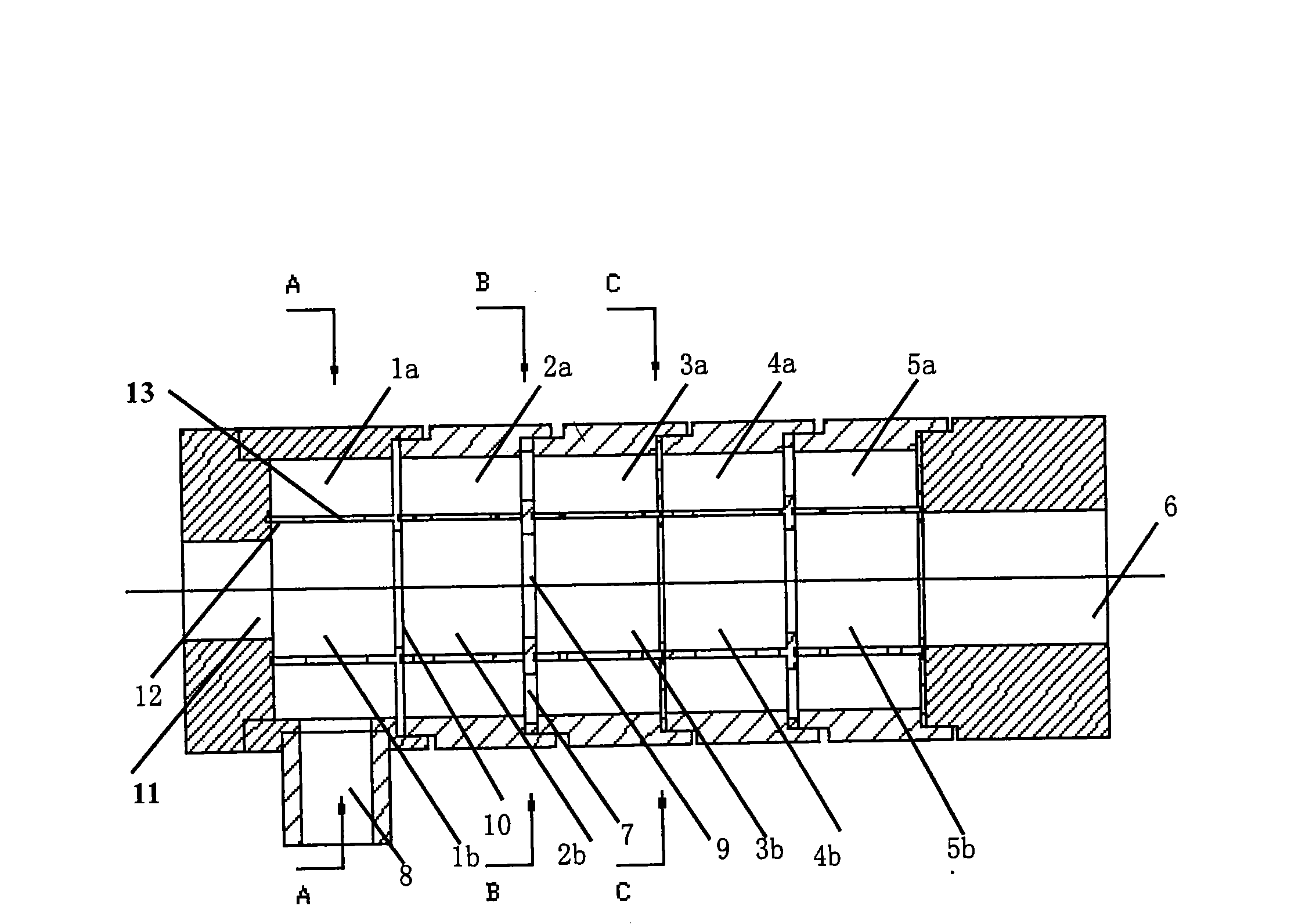
[0060] Such as figure 1 The embodiment of the present invention is used in the longitudinal sectional view of the coupling cavity interaction circuit structure of the cyclotron amplifier:

[0061] It is formed by cascading multiple composite cavities, each of which has an outer coaxial cavity a and an inner cylindrical cavity b, in the example five composite cavities:

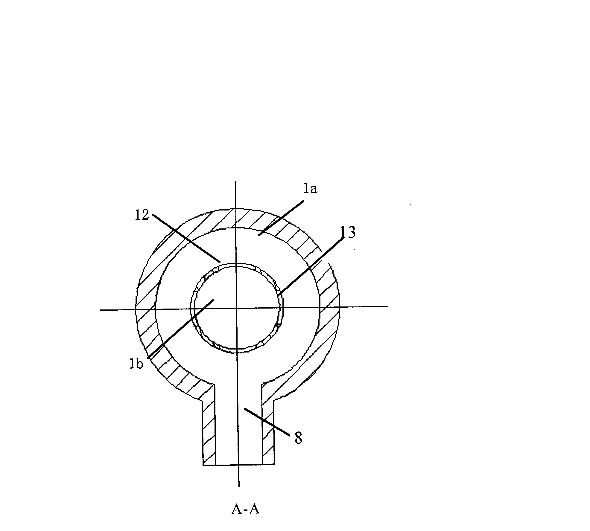
[0062] The first composite cavity includes: a first outer coaxial cavity 1a, a first inner cylindrical cavity 1b and a rectangular input waveguide 8;

[0063] The second composite cavity includes: a second outer coaxial cavity 2a, a second inner cylindrical cavity 2b;

[0064] The...


PUM


Abstract

The invention provides a coupled cavity for gyro-traveling wave amplifiers, which consists of a plurality of compound cavities in cascade connection, wherein each compound cavity has an outer coaxial cavity and an inner cylindrical cavity; the working mode of the inner cylindrical cavity is a TE0n circular electric mode; a common wall of a plurality of rectangular coupling holes is arranged between the inner cylindrical cavity and the outer coaxial cavity; two ends of the inner cylindrical cavity and the outer coaxial cavity in the axial direction are provided with vertical walls mutually perpendicular to the common wall; the vertical walls are axially provided with circular holes for providing electron beam channels and the coupling conversion or stop of working modes; and the vertical walls on the right side of the cavities with even serial numbers are provided with a plurality of sector coupling holes for the mode coupling of the adjacent outer coaxial cavities. In order to overcome the disadvantages that traveling wave interaction has relative instability and resonance interaction is narrow in frequency band, the coupled cavity transmits electromagnetic wave between every two adjacent resonant cavities so as to form the intercoupling resonance and alternate transmission-advance-coexistence of the electromagnetic in a plurality of resonant cavities, is used for high-frequency interaction circuits, enhances the interaction of electron beams with microwaves and millimeter waves, and expands working band.

Description

technical field [0001] The invention relates to electric vacuum device technology, in particular to a high-frequency interaction circuit for a cyclotron amplifier coupling cavity. Background technique [0002] At present, two amplification methods are mainly used in the cyclotron amplifier: one is the cycloklystron amplifier, which uses a resonant cavity to modulate the electron beam, so that the electron beam and the high-frequency field act synchronously in the angular direction to achieve high-frequency amplification; the other Second, the convoluted traveling wave amplifier, which adopts a waveguide structure to make the electron beam interact with the traveling wave high-frequency field angle synchronously, and realize high-frequency amplification. The cyclotron amplifier adopts a resonant cavity to obtain high output power, efficiency and gain, and has better stability. However, the use of a resonant cavity will narrow the operating frequency band of the swing amplifi...

Claims


Application Information

Patent Timeline
Patent Type & Authority Applications(China)
IPC IPC(8): H01P5/00
Inventor 罗积润栾远涛郭炜朱敏袁广江
Owner INST OF ELECTRONICS CHINESE ACAD OF SCI
Why Eureka
Try Eureka