


Quick Research
Generate reliable direction feasibility study reports for your R&D in just a few steps.

Technical Q&A
Discover and master advanced knowledge NOW. Basics, ideas, possibilities, all at once.

Find Solutions
As an expert in R&D theories, this can generate solutions to your technical problems instantly.

Evaluate Feasibility
Analyze your overall solution with one click, know your potential R&D risks in advance.

Monitor Landscape
Get weekly tech updates, stay abreast of the latest tech innovations and key insights.
Insulator for spark plug, and method for manufacturing spark plug
A manufacturing method and technology of insulators, which are applied in spark plug manufacturing, spark ignition controllers, spark plugs, etc., can solve problems such as increased manufacturing costs, and achieve the effects of guaranteed yield, high yield, and low manufacturing cost
- Summary
- Abstract
- Description
- Claims
- Application Information
AI Technical Summary
Problems solved by technology
Method used
Image

Examples
Embodiment 1
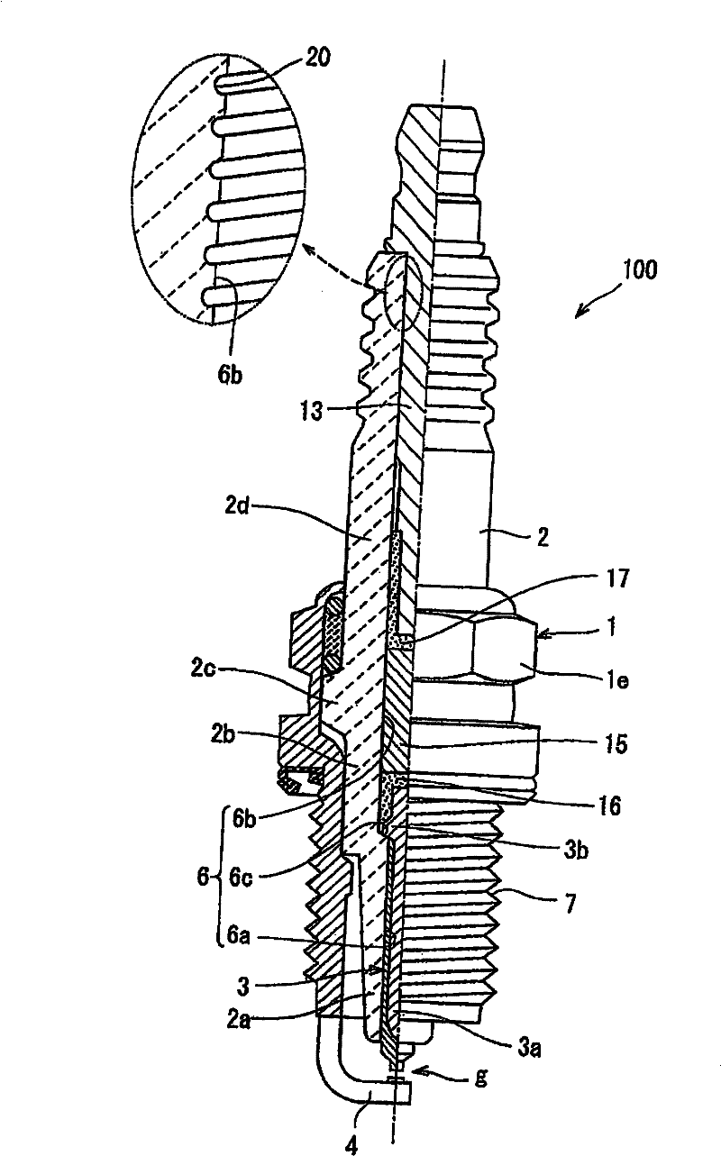
[0031] The manufacturing method of Example 1 is a method of manufacturing the insulator 2 which is an insulator for a spark plug. Since the spark plug 100 includes the insulator 2, first, the overall configuration of the spark plug 100 will be explained.
[0032] The spark plug 100 includes: a cylindrical metal shell 1; an insulator 2 fitted into the metal shell 1 so that its front end protrudes; a center electrode 3 provided in the insulator 2 with its front end protruding; Ground electrode 4 configured such that one end thereof is joined to metal shell 1 by welding or the like and the other end is laterally bent so that one side of the other end faces the front end portion of center electrode 3 .
[0033] A spark discharge gap g is formed between the ground electrode 4 and the center electrode 3 . The metal shell 1 is formed in a cylindrical shape from metal such as mild steel, and forms a housing for the spark plug 100 . The outer peripheral surface of the metal shell 1 i...
Embodiment 2
[0074] Although the manufacturing method of the second embodiment is similar to that of the first embodiment, the pressing pin 250 and the upper holding portion 286 are used in the second embodiment instead of the pressing pin 50 and the upper holding portion 86 of the first embodiment. Therefore, due to the difference in the structure of these components, the above-mentioned steps are also different. Hereinafter, differences from the manufacturing method of Embodiment 1 will be mainly described, and descriptions of the same steps as those of Embodiment 1 will be omitted or simplified. The same configurations as in Embodiment 1 are denoted by the same reference numerals, and descriptions of these same configurations are omitted.
[0075] Below, will refer to Figure 9 to Figure 13 A method of manufacturing the insulator 2 according to Example 2 will be described.
[0076] preparation steps
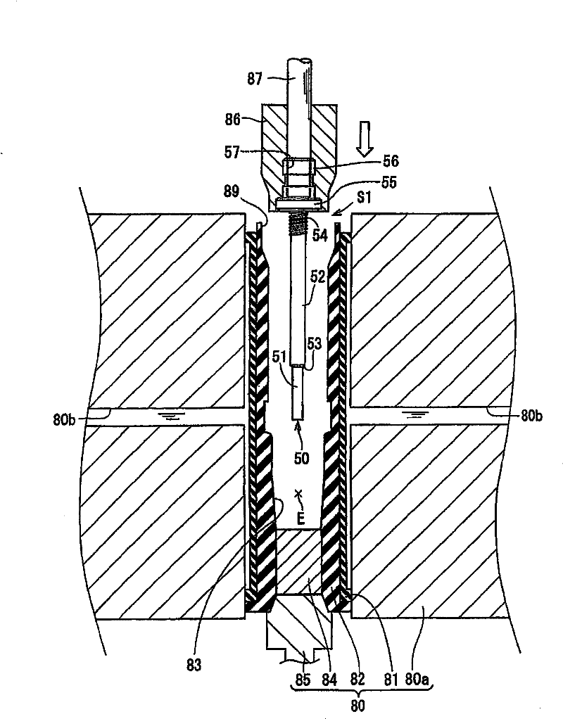
[0077] like Figure 9 As shown, in the preparation step, the pressing pin 250 an...
Embodiment 3
[0102] Although the manufacturing method of embodiment 3 is similar to the manufacturing method of embodiment 1, as Figure 14 and 15 Shown, changed the pressing pin configuration step of embodiment 1 (as image 3 shown) and powder filling steps (such as Figure 4 shown). Hereinafter, differences from the manufacturing method of Embodiment 1 will be mainly described, and descriptions of the same steps as those of Embodiment 1 will be omitted or simplified. In addition, the same configurations as those of Embodiment 1 are denoted by the same reference numerals, and descriptions of these same configurations are omitted.
[0103] preparation steps
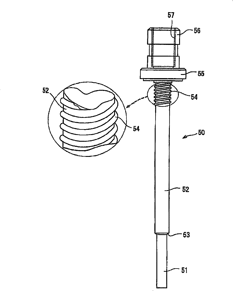
[0104] In the preparation step, similarly to Embodiment 1, the press pin 50 and the forming die 80 were prepared. As described in the preparation steps of Embodiment 1, the press pin 50 has: the first shaft portion 51 on the front end side in the axial direction; the second shaft portion 52 with a larger diameter; and the step...
PUM
| Property | Measurement | Unit |
|---|---|---|
| particle size | aaaaa | aaaaa |
| particle diameter | aaaaa | aaaaa |
Abstract
Description
Claims
Application Information
 - R&D Engineer
- R&D Manager
- IP Professional
- Industry Leading Data Capabilities
- Powerful AI technology
- Patent DNA Extraction
Browse by: Latest US Patents, China's latest patents, Technical Efficacy Thesaurus, Application Domain, Technology Topic, Popular Technical Reports.
© 2024 PatSnap. All rights reserved.Legal|Privacy policy|Modern Slavery Act Transparency Statement|Sitemap|About US| Contact US: help@patsnap.com