Heat dissipating combination

A heat dissipation device and heat sink technology, which is applied in the direction of elastic/clamping device, cooling/ventilation/heating transformation, circuit arrangement on the support structure, etc., which can solve the problems of user inconvenience, small screw size, and cumbersome installation process, etc.

Inactive Publication Date: 2009-09-23
FU ZHUN PRECISION IND SHENZHEN +1
View PDF0 Cites 7 Cited by
  • Summary
  • Abstract
  • Description
  • Claims
  • Application Information

AI Technical Summary

Problems solved by technology

[0004] However, due to the small size of the screws, it is necessary to use corresponding tools (such as screwdrivers) to operate the screws one by one when installing the radiator, which makes the entire installation process more complicated and inconvenient to the user.

Method used


Image

  • Heat dissipating combination
  • Heat dissipating combination
  • Heat dissipating combination

Examples


Embodiment Construction

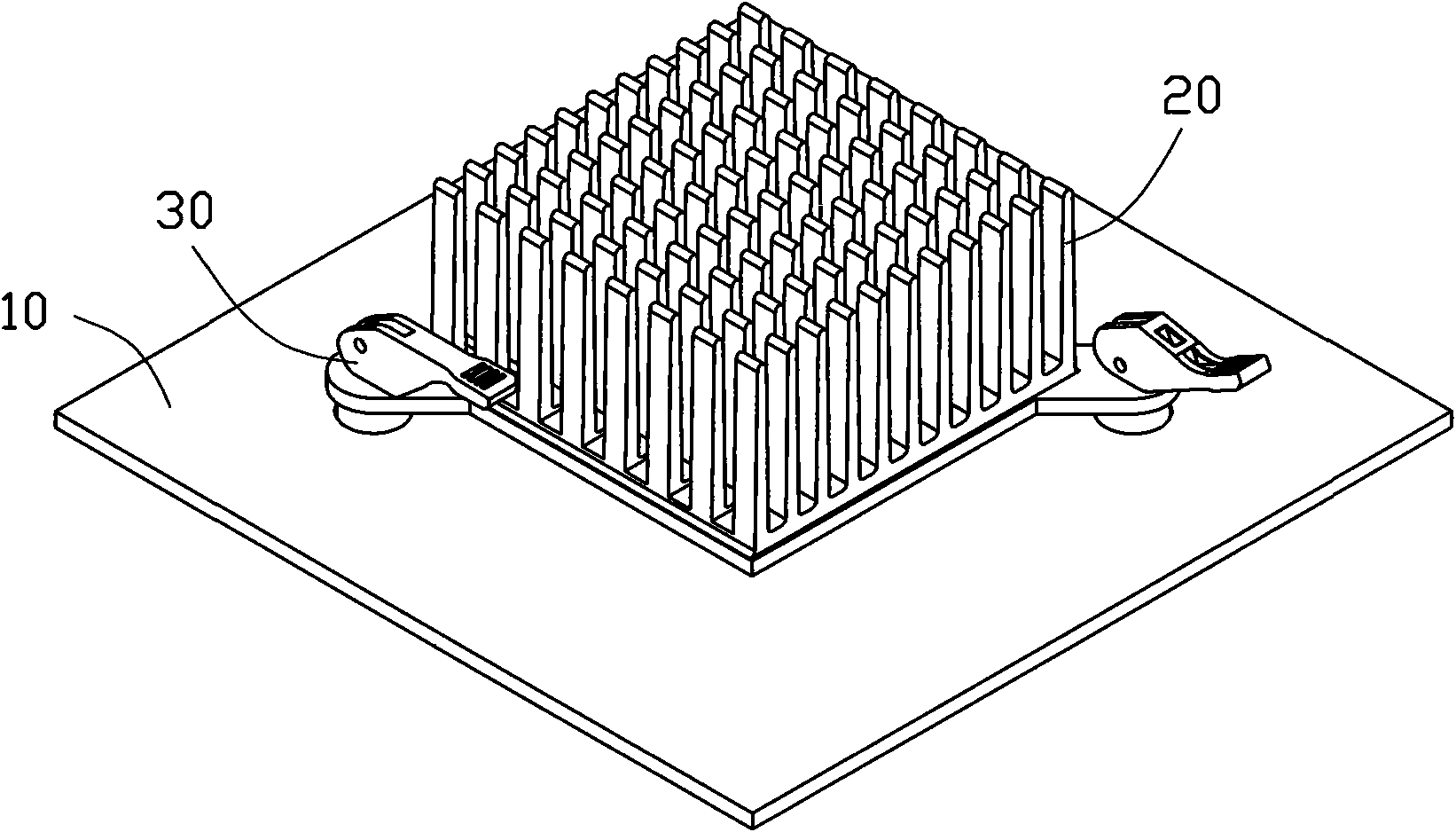
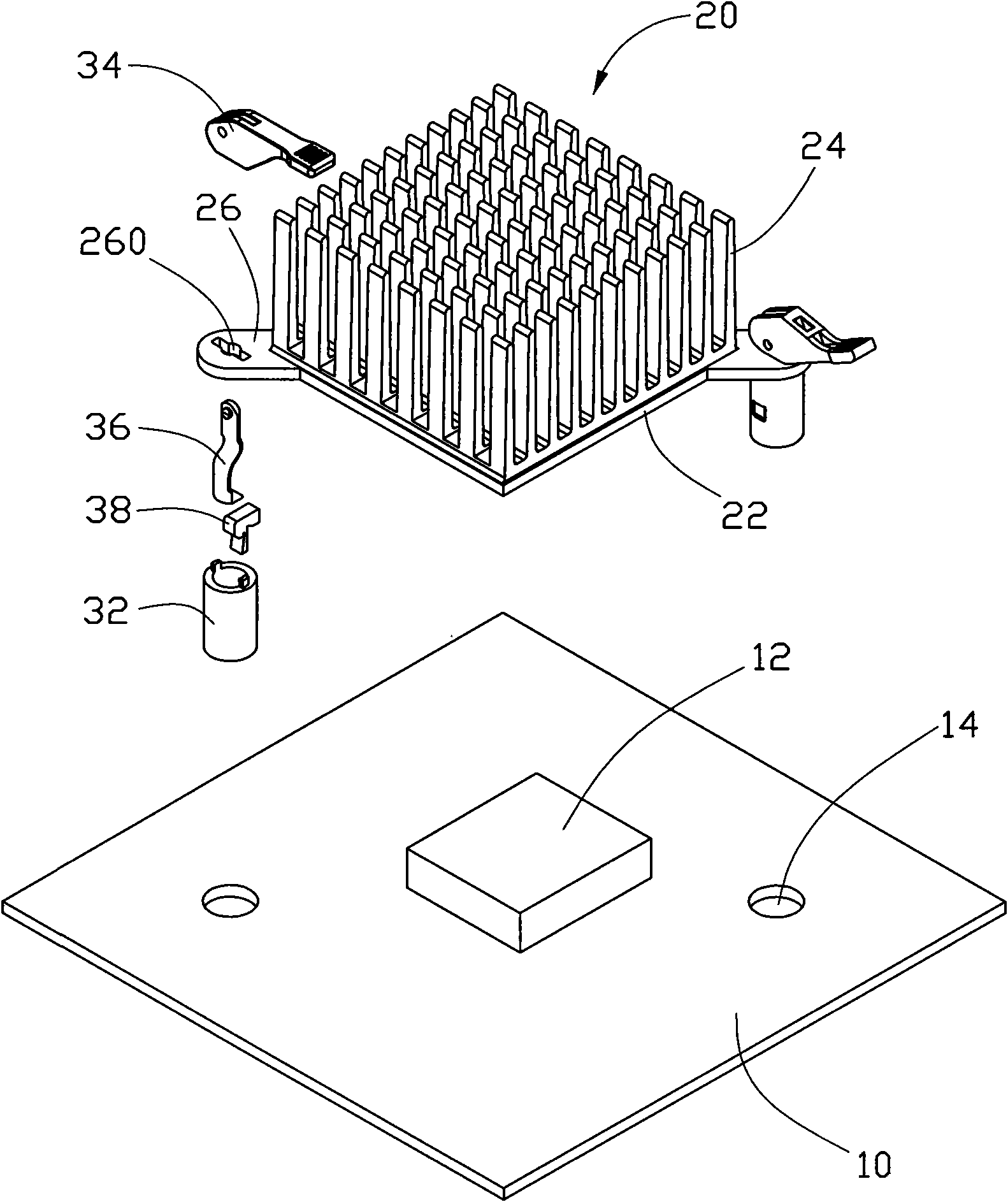
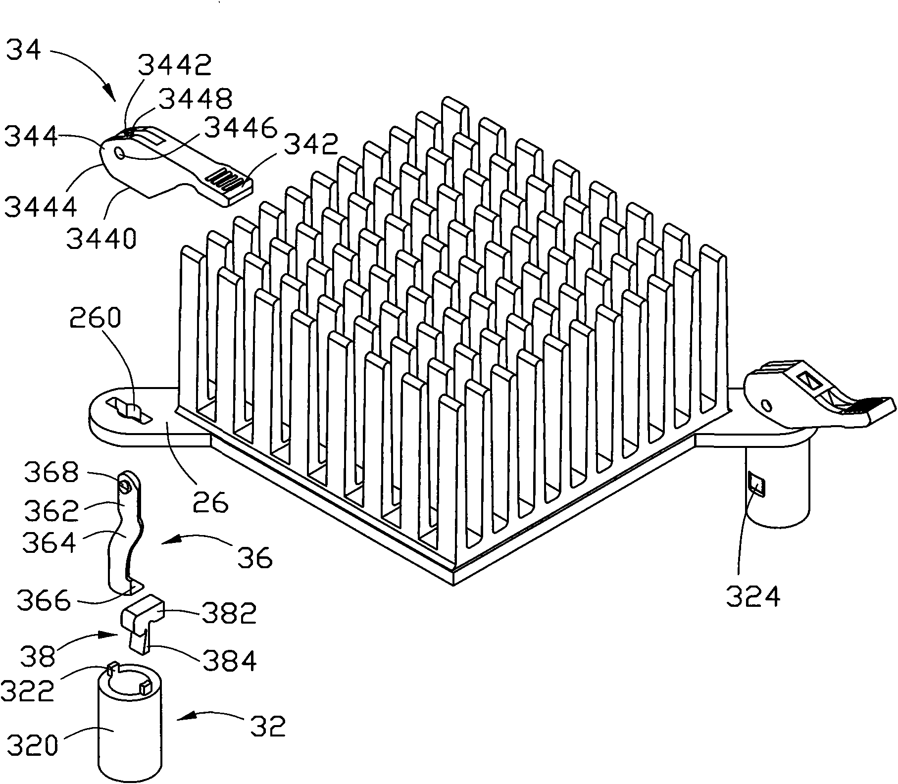
[0014] Such as figure 1 and 2 As shown, the heat sink assembly of the present invention is used to dissipate heat from the electronic components 12 mounted on the circuit board 10 , and includes a heat sink 20 and a plurality of fastening devices 30 for fixing the heat sink 20 to the circuit board 10 . Two through holes 14 corresponding to two opposite corners of the electronic component 12 are defined on the circuit board 10 for the corresponding structures of the fastening device 30 to pass through.

[0015] The heat sink 20 includes a rectangular bottom plate 22 and a plurality of fins 24 vertically extending upward from the top surface of the bottom plate 22 . The bottom plate 22 is used to contact the electronic components 12 to absorb the heat generated by them, and the fins 24 are used to dissipate the heat absorbed by the bottom plate 22 to the surrounding air, thereby realizing the heat dissipation of the electronic components 12 . Two pins 26 extend horizontally ou...


PUM


Abstract

A heat dissipating combination is used for dissipating heat for an electronic component arranged on a circuit board and comprises a radiator and a plurality of lock devices, wherein each lock device comprises a strut member inserted in the circuit board, a bolt accommodated in the strut member, a pull rod inserted in the strut member and pressed against the bolt, and an actuating piece pivoted on the pull rod and pressed against the radiator; and the pull rod is driven by the actuating piece to push the bolt to make the strut member extended to press against the circuit board. When the radiator is arranged on the circuit board, other tools are not used, so the process is simpler.

Description

technical field [0001] The invention relates to a cooling device combination, in particular to a cooling device combination for cooling electronic components. Background technique [0002] High-power electronic components such as computer central processing unit, north bridge chip, and graphics card will generate a lot of heat during operation. If the heat cannot be effectively dissipated, it will directly lead to a sharp rise in temperature, which will seriously affect the performance of electronic components. normal operation. Therefore, a heat sink is needed to dissipate heat from these electronic components. At the same time, in order to closely contact the heat sink with the electronic components, it is also necessary to use a fastening device that can fix the heat sink to the circuit board where the electronic components are located. [0003] A traditional cooling device assembly includes a heat sink and a number of screws used as fasteners. The radiator is placed o...

Claims


Application Information

Patent Timeline
Patent Type & Authority Applications(China)
IPC IPC(8): H05K7/20H05K7/12H01L23/40G06F1/20
CPCH01L2924/0002H01L23/4093Y10T24/44017H01L2924/00
Inventor 利民曹磊
Owner FU ZHUN PRECISION IND SHENZHEN
Why Eureka
Try Eureka