Method for grinding a machine part, and grinding machine for carrying out said method

A machine component and grinding technology, which is applied in the field of grinding machine components and grinding machines for implementing the same, can solve the problems of unattainable and unachievable grinding, and achieve the effect of improving size

Active Publication Date: 2009-09-23
ERWIN JUNKER MASCHNINENFAB
View PDF2 Cites 16 Cited by
  • Summary
  • Abstract
  • Description
  • Claims
  • Application Information

AI Technical Summary

Problems solved by technology

In this case, grinding cannot be achieved by known methods, since certain areas of the machine part cannot be reached with the usual clamping methods.
Especially when the machine part mentioned here is a transmission shaft, the required dimensional accuracy for machining and the accuracy of center positioning are very high, and only because of the tiny difference caused by insufficient accuracy in the grinding process, it is may lead to extremely adverse consequences under certain circumstances

Method used


Image

  • Method for grinding a machine part, and grinding machine for carrying out said method
  • Method for grinding a machine part, and grinding machine for carrying out said method
  • Method for grinding a machine part, and grinding machine for carrying out said method

Examples


Embodiment Construction

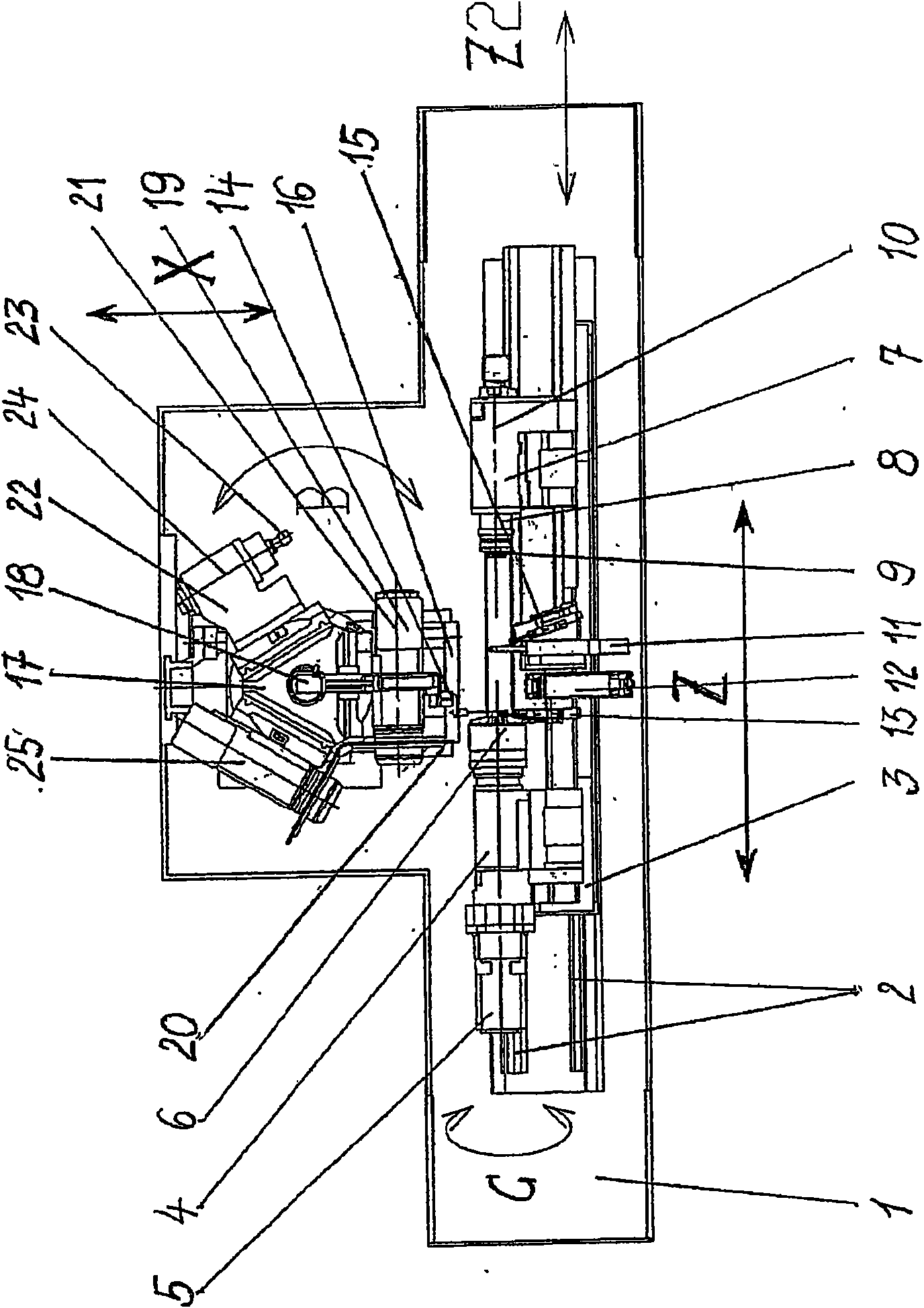
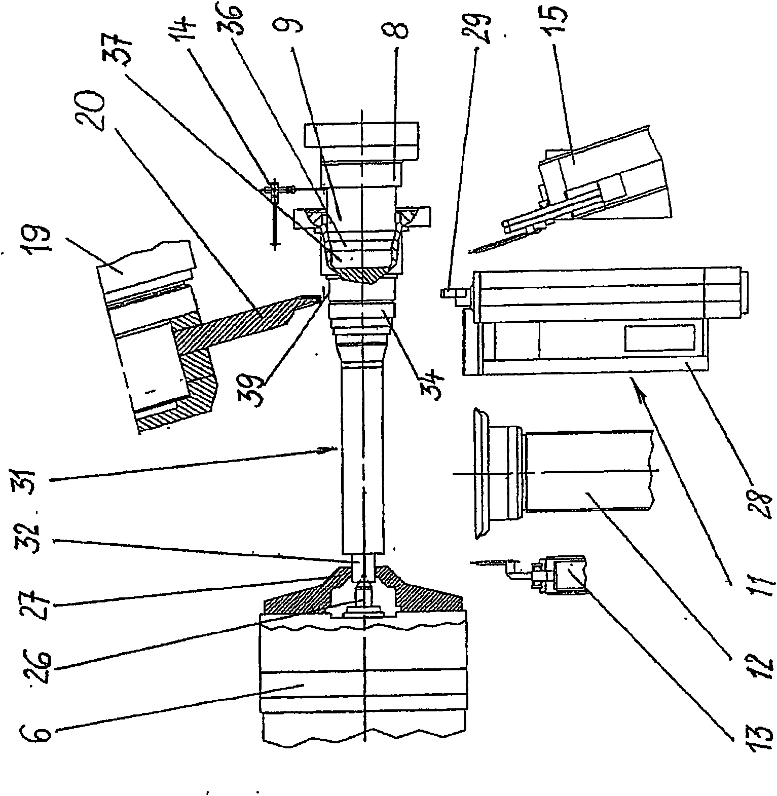
[0030] figure 1 and Figure 8 The grinding machine shown in is basically based on the typical construction of a universal, round and non-round grinding machine. On the bed 1 there is a guide rail 2, on which there is a grinding table 3 that can move longitudinally along the so-called Z2 axis, on which a headstock 4 with a drive motor 5 and a chuck 6 is arranged , the chuck 6 is used to clamp the machine parts 31, and the chuck 6 is provided with a centering tip 26 and detachable jaws 27 for this purpose (see Figures 2 to 4 ).

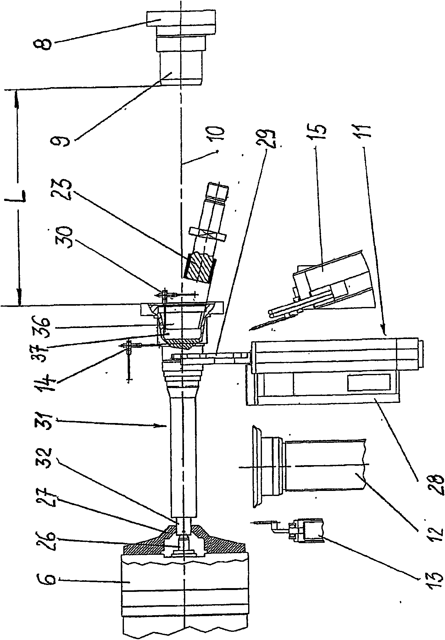
[0031] A tailstock 7 is provided coaxially with the headstock 4 and at a distance therefrom in the axial direction. Tailstock 7 has a conventional tailstock sleeve 8 terminating in a fitted sleeve tip 9 ( image 3 ). The tailstock 7 is moved longitudinally on the grinding table 3, wherein, as usual, the machine part 31 is clamped between the headstock 4 and the tailstock 7 with a common axis of rotation 10 (cf. Figure 2 to Figure 4 ).


PUM


Abstract

Disclosed is a method for grinding a machine part that is used as a drive shaft, for example, rotates about the longitudinal axis thereof during the grinding process, and is provided with a journal at one axial end thereof and a recess at the opposite end thereof. The grinding process is carried out in one and the same grinding machine. In said grinding method, the machine part is brought into different clamped states by means of a chuck of a workpiece spindle head (4) with releasable clamping jaws (6) and a centering tip, a backrest (11), and / or a tailstock quill (8). Changing the clamped states has the advantage that the machine part remains in the same position in a single grinding machine, i.e. the clamped position, in all the different clamped states such that more accurate sizes, shapes, and positions can be obtained in an economical manner and all areas of the machine part which are to be ground are successively accessible to the grinding disks.

Description

technical field [0001] The invention relates to a method for grinding a machine part driven to rotate about its longitudinal axis, said machine part having a journal at one of its axial ends and a journal at the opposite end an inner recess in which the outer surface is ground with the first grinding wheel and the peripheral surface of the inner recess is ground with the second grinding wheel, and provided for clamping the machine part during the grinding process Headstock, tailstock and at least one support; the invention also relates to a grinding machine belonging to the category of universal / circular / non-circular grinding machines for carrying out the method according to the invention. Background technique [0002] It is known to clamp the machine part with its ends between the headstock and the tailstock during the grinding process of such machine parts with a relatively complex design, and to use different grinding wheels for the different external contours. parts for...

Claims


Application Information

Patent Timeline
Patent Type & Authority Applications(China)
IPC IPC(8): B24B5/12
CPCB24B5/12
Inventor 埃尔温·容克尔
Owner ERWIN JUNKER MASCHNINENFAB
Why Eureka
Try Eureka