Bearing device for wheel

A bearing device and wheel technology, applied to bearings, axles, wheels, etc., can solve the problems of poor component management, poor workability, and large number of components, and achieve the effects of no noise, increased strength, and anti-rolling fatigue life

Active Publication Date: 2012-10-10
NTN CORP
View PDF7 Cites 0 Cited by
  • Summary
  • Abstract
  • Description
  • Claims
  • Application Information

AI Technical Summary

Problems solved by technology

Therefore, threading work is required during assembly, and workability is poor, and the number of parts is large, and parts management is poor.

Method used


Image

  • Bearing device for wheel
  • Bearing device for wheel
  • Bearing device for wheel

Examples


Embodiment Construction

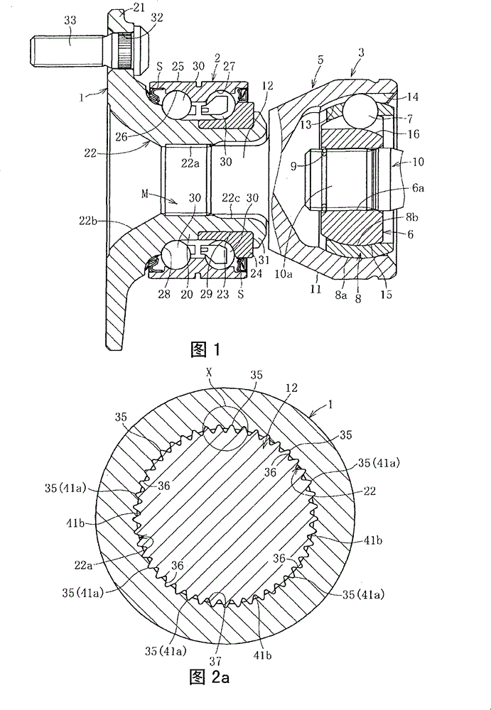
[0062] Below, based on Figure 1 to Figure 12 Embodiments of the present invention will be described. figure 1 A wheel bearing device according to a first embodiment is shown, in which a hub wheel 1 , a plurality of rows of rolling bearings 2 , and a constant velocity universal joint 3 are integrated.

[0063] The main components constituting the constant velocity universal joint 3 are: an outer ring 5 as an outer joint member; an inner ring 6 as an inner joint member arranged inside the outer ring 5; and a plurality of balls 7 for transmitting torque; and a cage 8 interposed between the outer ring 5 and the inner ring 6 to hold the balls 7 . The inner ring 6 is coupled to the shaft 10 by press-fitting the end portion 10a of the shaft 10 into the inner diameter 6a of the shaft hole 6a and spline-fitting, so that torque can be transmitted. In addition, an end portion 10a of the shaft 10 is fitted with a locking wheel 9 for shaft detachment prevention.

[0064] The outer rin...


PUM


Abstract

A bearing device for a wheel, in which circumferential play is suppressed and which has excellent workability of connection between a hub ring and an outer joint member of a constant velocity universal joint. In the bearing device for a wheel, a stem shaft (12), which is fitted in a hole (22) of the hub ring (1), of the outer joint member of the constant velocity universal joint (3) is integratedwith a hub ring (1) via a depression / projection fitting structure (M). In the depression / projection fitting structure (M), the entire part of a portion (38) of a projection (35), which portion is to be fitted to a depression, is in intimate contact with a corresponding depression section (36).

Description

technical field [0001] The present invention relates to a wheel bearing device for rotatably supporting a wheel on a vehicle such as an automobile. Background technique [0002] Bearing devices for wheels have developed the following second to fourth generation devices based on the structure called the first generation of multi-row rolling bearings alone, that is, the second generation with the body mounting flange integrated in the outer part; The outer circumference of the hub wheel with the flange mounted on the car body, the third generation in which the inner rolling surface is integrally formed on one side of the multi-row rolling bearing; and the constant velocity universal joint is integrally formed on the hub wheel, and the constant velocity universal joint is formed in the The outer periphery of the outer joint member integrally forms the fourth generation of the other inner rolling surface of the multi-row rolling bearing. [0003] For example, Patent Document 1 ...

Claims


Application Information

Patent Timeline
Patent Type & Authority Patents(China)
IPC IPC(8): B60B35/14B60B27/00F16C19/18F16C33/64F16C35/073
CPCY02T10/86
Inventor 福村善一藏久昭友上真河村浩志山内清茂小泽仁博中川亮浅野祐一
Owner NTN CORP
Why Eureka
Try Eureka