
Apparatus and method for generating micro bubbles

A micro-bubble generation and micro-bubble technology, applied in chemical instruments and methods, transportation and packaging, mixers, etc., can solve the problems of increased cost, large noise and vibration, difficult operation, etc., and achieve the effect of low cost

Inactive Publication Date: 2009-09-23
G & G KOREA
View PDF0 Cites 27 Cited by
  • Summary
  • Abstract
  • Description
  • Claims
  • Application Information

AI Technical Summary

Problems solved by technology

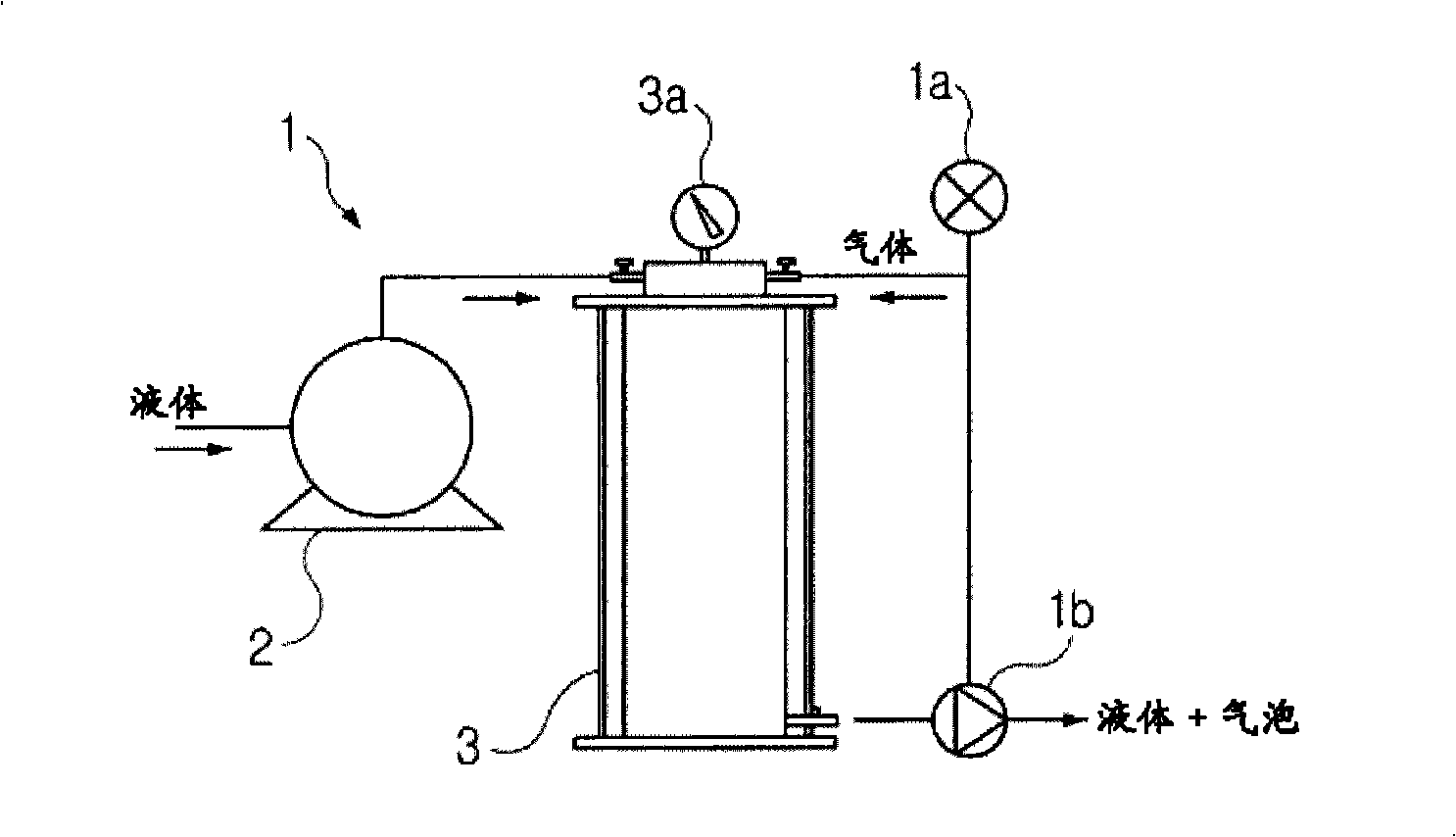
[0013] In this conventional air bubble generating device, its disadvantages are that the structure of the device is complicated, the operation is difficult, and a compressor must be provided as a necessary component, the noise and vibration caused by the operation are relatively large, and the cost of consumption is also greatly increased.

Method used


Image

  • Apparatus and method for generating micro bubbles
  • Apparatus and method for generating micro bubbles
  • Apparatus and method for generating micro bubbles

Examples


Embodiment 1

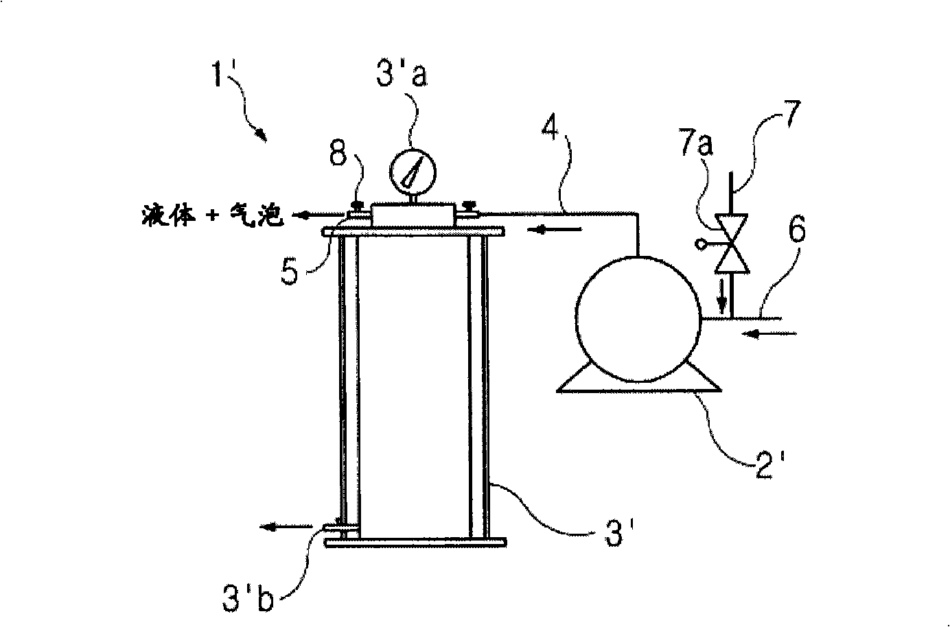
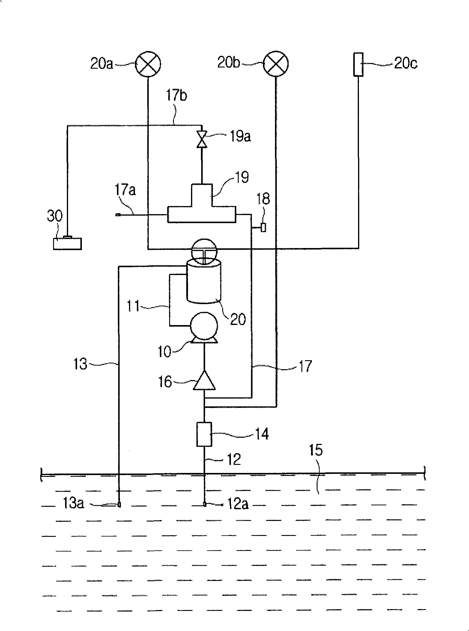
[0045] image 3 Shown is the schematic structure according to the micro-bubble generating device of the present invention, as shown in the figure, its basic structure of the micro-bubble generating device of the present invention is a pump 10 and corresponds to the above-mentioned figure 2 The pressurized tank 20 of the middle mixing chamber 3'.

[0046] The outlet of the pump 10 is connected to the inlet of the pressurized tank 20 through a pipe (water pipe) 11, and the inlet of the pump 10 and the outlet of the pressurized tank 20 lead to pipes (water pipes) 12, 13 extending into the water storage tank 15, respectively. .

[0047] In order to regulate the water flowing in from the water storage tank 15, the present invention is provided with a flow regulating valve 14 and a check valve 16 between the water inlet 12a of the water pipe 12 and the pump 10. And between the water inlet 12a of the above-mentioned water pipe 12 and the pump 10, a suction pipe 17 for sucking air ...

Embodiment 2

[0062] Figure 5 for image 3 A schematic diagram of a variant of the pressurized tank shown, Figure 6 for Figure 5 A cross-sectional view of the internal structure of the pressurized tank shown.

[0063] As shown in the figure, the pressurized tank 20' has a dual chamber structure of an inner chamber 27 and an outer chamber 28. The upper end of the outer chamber 28 is sealed, and the inner chamber 27 is separated from the inner wall of the outer chamber 28 and has an open upper end. The surface of the external chamber 28 is provided with connections to the respective water pipes 11, 13 (refer to image 3 ) of the inlet 21' and outlet 22', the inlet 21' and the outlet 22' extend toward the inside of the pressurized tank 20' with pipes 20'a, 20'b.

[0064] Most suitably, the inflow pipe 20'a extending from the inflow port 21' extends to the bottom of the inner chamber 27, and the outflow pipe 20'b extending from the outflow port 22' passes through the gap between the inn...


PUM


Abstract

Disclosed is an apparatus for generating a large quantity of micro-bubbles. The micro-bubble generating apparatus includes: a pump for inhaling and mixing a gas and a liquid; a mixing chamber for remixing the gas and the liquid pressurized and fed from the pump, and a nozzle for discharging the mixture of the gas and liquid, which is formed by remixing the gas and the liquid in the mixing chamber. The mixing chamber is provided with one or more partitions, each of which is formed with one or more holes, the mixture of the liquid and gas flowing through the holes. According to the present invention, a large quantity of micro-bubbles according to a dissolved air floating (DAF) process with low costs by employing the mixing chamber modified as described above.

Description

technical field [0001] The present invention relates to the generation of micro-bubbles, in particular to a micro-bubble generating device which utilizes a pump and a deformed pressurized tank to generate a large number of ultra-fine bubbles by Dissolved Air Flotation (DAF) and a device utilizing the device. Microbubble generation method. Background technique [0002] As we all know, microbubbles (usually called Microbubbles) are a general term for bubbles with a diameter of less than 50 μm. The generation of microbubbles is mainly realized by the method of pressurized dissolution, and the generation of microbubbles in the present invention is specifically formed by dissolved air flotation (DAF). [0003] Dissolved air flotation (DAF) is a water treatment method, which fully dissolves air in water with high pressure, injects it into the raw water to be treated, and obtains decompressed water in the raw water to make supersaturated The air is formed as microbubbles, which c...

Claims


Application Information

Patent Timeline
IPC IPC(8): C02F1/74
CPCB01F2003/04858C02F1/78B01F5/0682B01F3/0446B01F5/0688B03D1/028B03D1/14B03D1/1431C02F1/727C02F1/74B03D1/247C02F1/24B01F23/232B01F23/2373B01F25/45B01F25/4521B01F23/2326C02F1/72
Inventor 朴在燮李宽雨
Owner G & G KOREA
Learn More