LS control arrangement

A control device and fluid control technology, applied in fluid pressure actuators, servo motor components, mechanical equipment, etc., can solve troublesome problems

Inactive Publication Date: 2013-05-29
ROBERT BOSCH GMBH
View PDF3 Cites 0 Cited by
  • Summary
  • Abstract
  • Description
  • Claims
  • Application Information

AI Technical Summary

Problems solved by technology

The aforementioned control channels and nozzles are integrated in the spool, so that the manufacture of the spool is complex due to the design of the throttle cross-section and the connecting channels

Method used


Image

  • LS control arrangement
  • LS control arrangement
  • LS control arrangement

Examples


Embodiment Construction

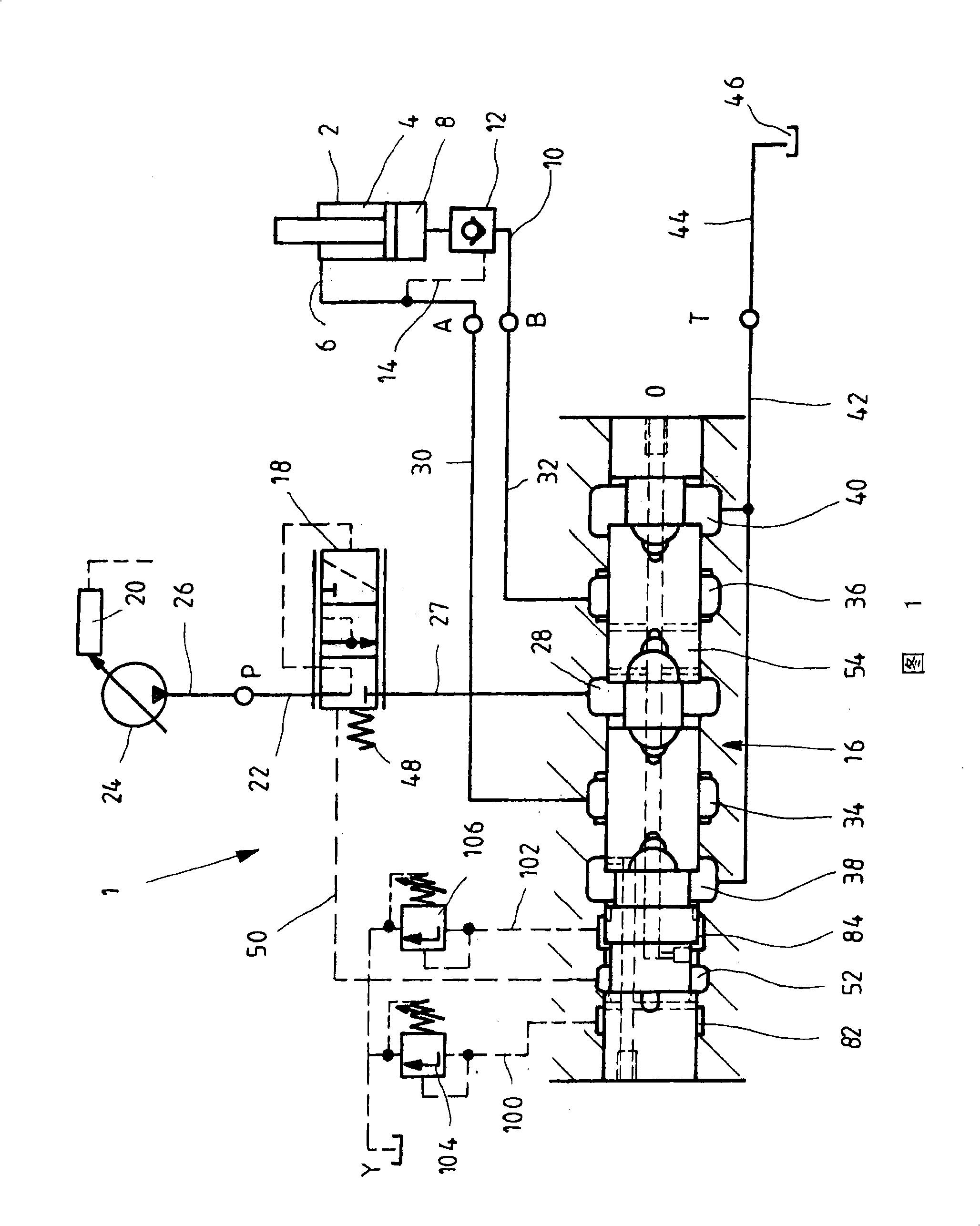
[0027] figure 1The shown system diagram of an LS control device can be designed, for example, as a valve plate of a mobile control block (Mobilsteuerblock) for triggering the hydraulic loading of the bending arm of a mobile work tool, such as a truck-loading crane . Such an LS control device 1 has a pressure connection P, a tank connection T as well as two working connections A, B and at least one leakage connection Y as well as a not shown LS connection. A load is connected to the two working joints A and B, here it is a differential cylinder 2, its annular chamber 4 is connected to the joint A through a working pipeline 6, and its bottom side cylinder chamber 8 is passed through a working The pipeline 10 is connected to the working joint B. In the working line 10 there is a lowering brake valve 12, which can be released by the pressure in the working line 6 when the differential cylinder 2 is moved in, so that the pressure medium can flow out of the then reduced cylinder c...


PUM


Abstract

An LS control system is disclosed that includes an inlet metering orifice and a pressure compensator, via which the pressure drop across the inlet metering orifice may be held constant. The signalling pressure that acts on the pressure compensator in the opening direction may be varied as a function of the displacement in order to prevent the system from oscillating if a negative load should occur.

Description

technical field [0001] The invention relates to an LS control device for supplying a hydraulic load with pressure medium. Background technique [0002] This type of LS control device is used in particular for controlling hydraulic loads of mobile work tools. DE 197 15 020 A1 discloses an LS control unit in which the load is supplied with pressure medium via an LS directional valve. Proportional directional control valves have a control slide which, together with a valve housing, forms a direction component and a speed component. The direction component controls the flow of the pressure medium to or from the load, while the speed component regulates the flow of the pressure medium. In the known solution, the velocity components are each formed by an adjustable measuring orifice arranged in the inflow and in the outflow line, the opening cross-section of which can be varied by axial displacement of the control slide. At least one pressure scale is connected in front of the ...

Claims


Application Information

Patent Timeline
Patent Type & Authority Patents(China)
IPC IPC(8): F15B13/04
CPCF15B13/0417
Inventor A·斯特尔瓦根
Owner ROBERT BOSCH GMBH
Why Eureka
Try Eureka