Process for producing magnet
A manufacturing method and magnet technology, which is applied in the field of magnet manufacturing, can solve problems such as the decrease of Br and the reduction of saturation magnetization of compounds, and achieve the effects of sufficient squareness ratio, small decline in magnetic properties, and large squareness ratio
- Summary
- Abstract
- Description
- Claims
- Application Information
AI Technical Summary
Problems solved by technology
Method used
Image

Examples
Embodiment 1
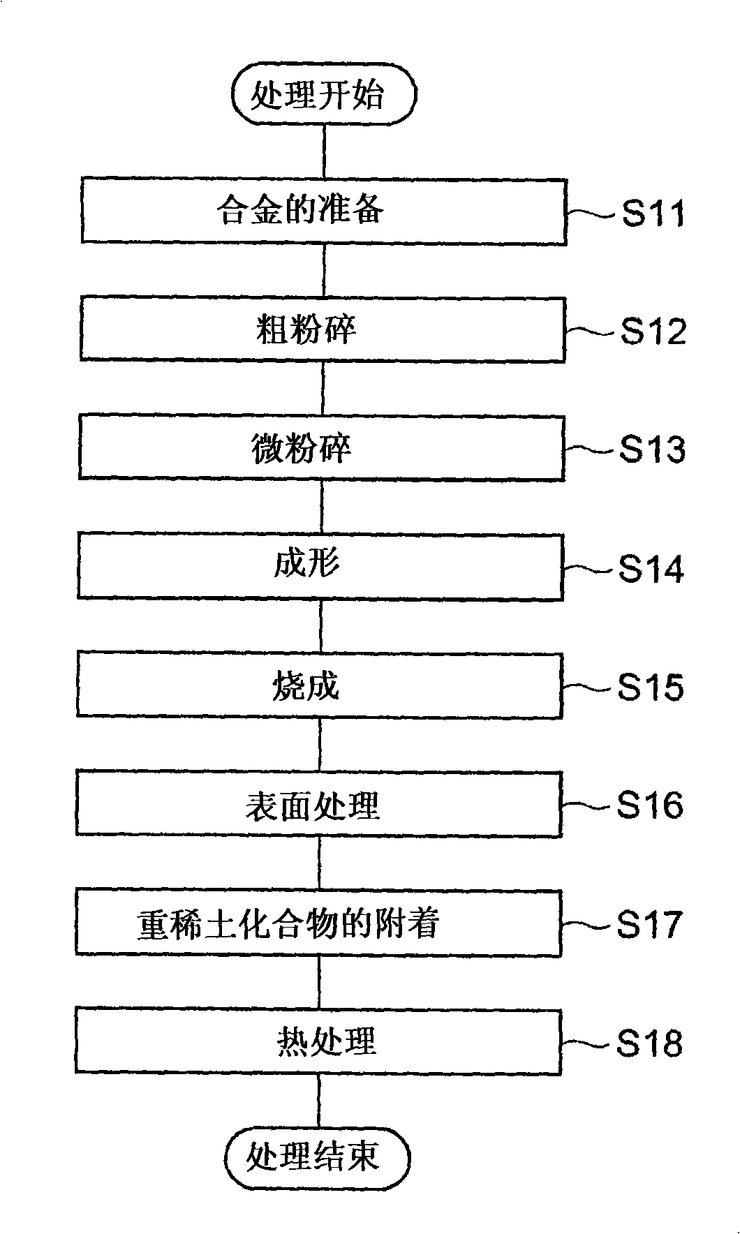
[0051] First, a raw material alloy is prepared so as to obtain an alloy having a composition of 24.00wt% Nd-1.00wt% Dy-5.30wt% Pr-0.450wt% Co-0.18wt% Al-0.06wt% Cu-1.00wt% B-balance Fe Rare earth magnets. As the raw material alloy, two kinds of a main phase-based alloy for mainly forming the main phase of the magnet and a grain boundary-based alloy for mainly forming grain boundaries were prepared. Subsequently, these raw material alloys were coarsely pulverized by hydrogen pulverization, and then subjected to high-pressure N 2 Air jet mill pulverization, each made into a fine powder with an average particle diameter D = 4 μm.
[0052] The obtained fine powder of the main phase alloy and the fine powder of the grain boundary alloy were mixed at a ratio of the former: the latter = 95:5 to prepare a magnetic powder as a raw material powder of a rare earth magnet. Subsequently, using the magnetic powder, the molding pressure is 1.2t / cm 2 , Molding in a magnetic field was perfo...
Embodiment 2、3
[0057] Rare earth magnets were produced in the same manner as in Example 1, except that the dried sintered bodies were heat-treated at 900°C (Example 2) and 1000°C (Example 3), respectively.
Embodiment 4~6
[0078] First, a raw material alloy was prepared so as to obtain a rare earth magnet having a composition of 26.50wt% Nd-3.50wt% Dy-0.50wt% Co-0.22wt% Al-0.07wt% Cu-0.92wt% B-balance Fe. As the raw material alloy, two kinds of a main phase-based alloy for mainly forming the main phase of the magnet and a grain boundary-based alloy for mainly forming grain boundaries were prepared. Subsequently, these raw material alloys were coarsely pulverized by hydrogen pulverization, and then subjected to high-pressure N 2 Air jet mill pulverization to obtain fine powders with an average particle diameter D=4 μm.
[0079] The obtained fine powder of the main phase alloy and the fine powder of the grain boundary alloy were mixed at a ratio of the former: the latter = 95:5 to prepare a magnetic powder as a raw material powder of a rare earth magnet. Subsequently, using the magnetic powder, the molding pressure is 1.2t / cm 2 , Molding in a magnetic field was performed under the condition of a...
PUM
| Property | Measurement | Unit |
|---|---|---|
| particle size | aaaaa | aaaaa |
| particle diameter | aaaaa | aaaaa |
| particle size | aaaaa | aaaaa |
Abstract
Description
Claims
Application Information
 - R&D
- Intellectual Property
- Life Sciences
- Materials
- Tech Scout
- Unparalleled Data Quality
- Higher Quality Content
- 60% Fewer Hallucinations
Browse by: Latest US Patents, China's latest patents, Technical Efficacy Thesaurus, Application Domain, Technology Topic, Popular Technical Reports.
© 2025 PatSnap. All rights reserved.Legal|Privacy policy|Modern Slavery Act Transparency Statement|Sitemap|About US| Contact US: help@patsnap.com