Permanent magnet, and motor and generator using the permanent magnet
A technology of permanent magnets and generators, applied to magnetic objects, magnetic circuits characterized by magnetic materials, circuits, etc., can solve problems such as deterioration of hysteresis loop square ratio and reduction of coercive force
- Summary
- Abstract
- Description
- Claims
- Application Information
AI Technical Summary
Problems solved by technology
Method used
Image

Examples
Embodiment 1
[0057] Each raw material was weighed and mixed at a predetermined ratio, and cast after high-frequency dissolution in an Ar gas atmosphere to produce an alloy ingot. The alloy ingot is coarsely pulverized and then finely pulverized by a jet mill to prepare an alloy powder. The alloy powder is press-molded in a magnetic field to produce a compression-molded body. The compression-molded body of the alloy powder was placed in a firing furnace, heated up to 1190° C. in an Ar atmosphere, and kept at this temperature for 3 hours for sintering. Next, after performing solution treatment by holding at 1140° C. for 10 hours, it was rapidly cooled to 990° C. at a cooling rate of −250° C. / min, and further cooled to room temperature.
[0058] Next, the temperature of the solution-treated sintered body was raised to 800° C., kept at this temperature for 60 hours, and subjected to aging treatment. The aging-treated sintered body was slowly cooled to 450°C at a rate of -0.3°C / min, kept at t...
Embodiment 2、3
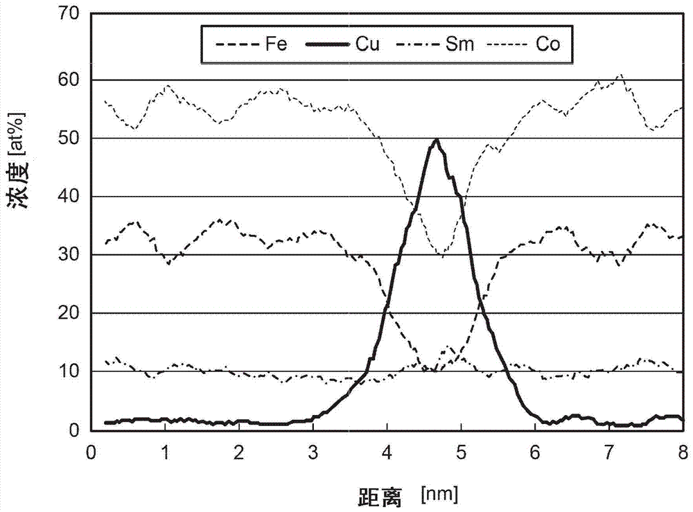
[0064] Under the same conditions as in Example 1, sintered magnets having the compositions shown in Table 1 were produced. The Cu concentration distribution, coercive force, residual magnetization, and squareness ratio in the cell wall phase of the obtained sintered magnet were measured and evaluated in the same manner as in Example 1. The measurement results are shown in Table 3. In addition, from the measurement results of the Cu concentration distribution in the cell wall phase, it was confirmed that the sintered magnets of Examples 2 and 3 had a region where the Cu concentration exceeded 40 atomic % near the center of the cell wall phase, as in Example 1.
Embodiment 4
[0066] Each raw material was weighed and mixed at a predetermined ratio, and cast to produce an alloy ingot after high-frequency dissolution in an Ar gas atmosphere. The alloy ingot is coarsely pulverized, followed by fine pulverization with a jet mill to prepare alloy powder. The alloy powder is press-molded in a magnetic field to produce a compression-molded body. The compression-molded body of the alloy powder was placed in a firing furnace, heated up to 1180° C. in an Ar atmosphere, and kept at this temperature for 5 hours for sintering. Next, after performing solution treatment by holding at 1130° C. for 12 hours, it was rapidly cooled to 980° C. at a cooling rate of −300° C. / min, and further cooled to room temperature.
[0067] Next, the temperature of the sintered body after the solution treatment was raised to 790° C., maintained at this temperature for 80 hours, and subjected to aging treatment. The aging-treated sintered body was slowly cooled to 480°C at a rate of...
PUM
| Property | Measurement | Unit |
|---|---|---|
| particle size | aaaaa | aaaaa |
Abstract
Description
Claims
Application Information
 - R&D
- Intellectual Property
- Life Sciences
- Materials
- Tech Scout
- Unparalleled Data Quality
- Higher Quality Content
- 60% Fewer Hallucinations
Browse by: Latest US Patents, China's latest patents, Technical Efficacy Thesaurus, Application Domain, Technology Topic, Popular Technical Reports.
© 2025 PatSnap. All rights reserved.Legal|Privacy policy|Modern Slavery Act Transparency Statement|Sitemap|About US| Contact US: help@patsnap.com