Monitoring a flexible power cable

A power cable and cable technology, applied in the field of bending and straining systems, can solve problems such as increasing installation complexity and achieve low cost effects

Inactive Publication Date: 2009-09-30
ABB TECH AG
View PDF2 Cites 16 Cited by
  • Summary
  • Abstract
  • Description
  • Claims
  • Application Information

AI Technical Summary

Problems solved by technology

The obvious drawback of this solution is the increased installation complexity and the complexity of using several different optical cables to measure a bending axis

Method used


Image

  • Monitoring a flexible power cable
  • Monitoring a flexible power cable
  • Monitoring a flexible power cable

Examples


Embodiment Construction

[0040] A detailed description of the preferred embodiments is provided herein. However, it should be understood that the invention can be embodied in various forms. Therefore, specific details disclosed herein are not to be interpreted as limiting, but rather as a basis for the claims and as a representative basis for teaching one skilled in the art to employ the invention in substantially any suitable specific system, structure or manner. .

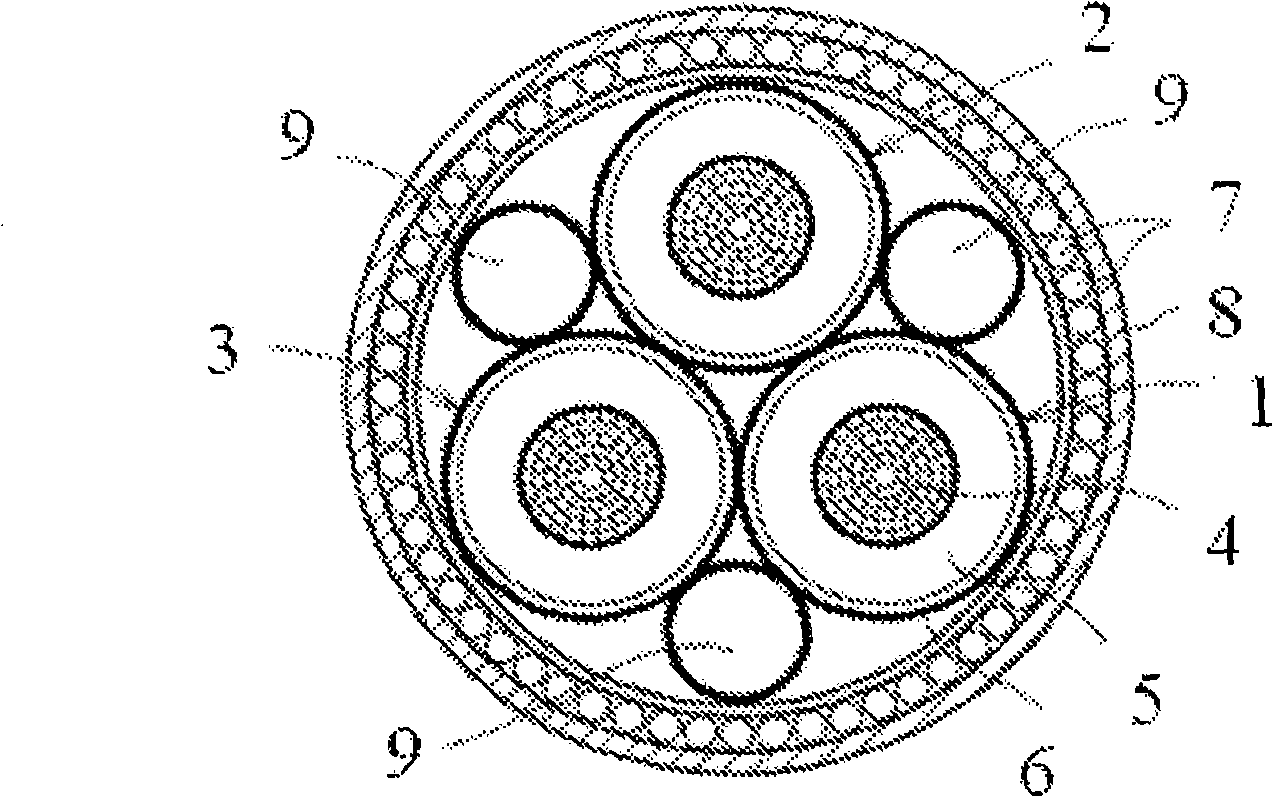
[0041] figure 1 A schematic diagram showing a cross-section of a high voltage power cable on which the invention can be used. High voltage power cables can consist of one, two, three or more single conductor cables. figure 1 The power cable shown consists of three single-conductor cable cores 1-3. Each single-conductor cable core has a metallic center conductor 4 enclosed in an insulating layer 5 surrounded by a cable shield 6 . The cable cores are provided with one or more common outer layers, such as an armor wire 7 and an outer s...


PUM


Abstract

An offshore monitoring system, for an electrical power cable connected between a fixed point and a movable point, or for an electrical power cable connecting two movable points. The system comprises at least one optical fiber acting as a continuously distributed strain measurement sensor attached to or arranged in said power cable, a device arranged for sending optical signals and a device arranged for receiving optical signals to determine the time variant bending of said power cable.

Description

technical field [0001] The present invention relates to a system for monitoring the bending and strain of a power cable connected to a mobile offshore platform by measuring the strain of an optical fiber attached to or incorporated into the power cable. Background technique [0002] Offshore installations, such as oil / gas rigs, processing platforms, semi-submersible installations, etc. are increasingly connected by power cables to onshore installations, fixed subsea installations or other offshore installations. In the case of floating rigs, power cables are subject to repeated motion and bending due to wave roll, wind pressure and / or tidal motion. [0003] In order to withstand the movements of floating offshore installations, power cables must be somewhat flexible. However, the movement of the facility and the resulting bending of the power cables can limit the useful life of the cables. The service life of a power cable is determined not only by the number of bends it i...

Claims


Application Information

Patent Timeline
Patent Type & Authority Applications(China)
IPC IPC(8): H01B11/22G01B11/00G02B6/00
CPCG02B6/4417H01B9/005H01B7/32G01M11/086G01M5/0041G01M5/0091G01M11/085
Inventor T·沃齐克
Owner ABB TECH AG
Why Eureka
Try Eureka