
Machine tool

A technology for changing machine tools and tools, applied in the field of machine tools, can solve the problems of prolonging the production efficiency of machine tools and reducing the action time of tool changing devices.

Active Publication Date: 2009-10-07
BROTHER KOGYO KK
View PDF0 Cites 11 Cited by
  • Summary
  • Abstract
  • Description
  • Claims
  • Application Information

AI Technical Summary

Problems solved by technology

The productivity of the machine tool is greatly reduced due to the prolongation of the operation time of the tool changer every time a tool is changed

Method used


Image

  • Machine tool
  • Machine tool
  • Machine tool

Examples


Embodiment Construction

[0026] DETAILED DESCRIPTION OF THE INVENTION The present invention will be described in detail below with reference to the accompanying drawings showing preferred embodiments.

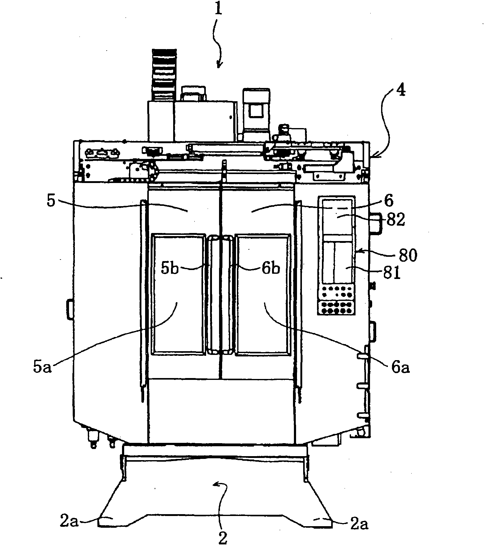
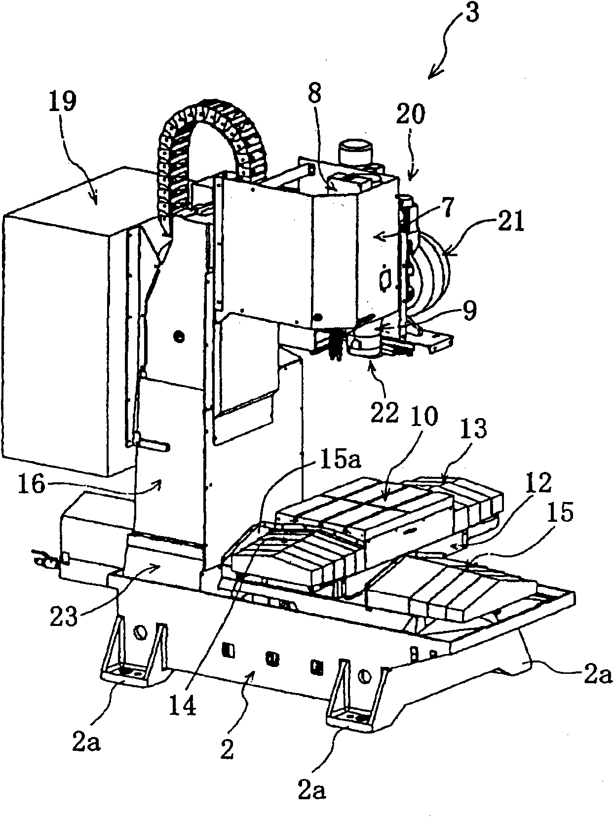
[0027] Such as figure 1 As shown, a machining center 1 (a machine tool according to the present invention) includes a base 2 made of cast iron and a protective shutter 4 covering the upper part of the base 2 . The protective baffle 4 will be arranged on the machine tool body 3 on the abutment 2 (referring to figure 2 ) surrounded by the outside.

[0028] Such as figure 1 , figure 2 As shown, the base 2 is a rectangular parallelepiped casting long in the Y-axis direction (front-back direction). The base 2 is arranged on the floor surface through the leg portions 2a, and the leg portions 2a are arranged at four corners of the lower part. The height of the foot portion 2a is adjustable. The height adjustment of the foot portion 2a is for the workbench 10 of the machine tool body 3 (refer to figu...


PUM


Abstract

A machine tool stores the time for determining the clogging status of the filter. A control device performs tool replacement to the tool replacement device for a longer time only if the pass time is long from the stored time of the time storing section. A pressure difference detecting sensor accurately detects the fore-and-after pressure difference of the filter in the longer replacement time. A judgement section accurately determines the clogging of the filter based on the exact pressure difference detected by the pressure difference detecting sensor. The longer replacement action of the tool replacement device is performed only after a preset-time is passed after the last clogging judgement has been performed. The production efficiency of the machine tool is scarcely declined.

Description

technical field [0001] The present invention relates to a machine tool including: a tool changing device for changing a tool between a tool storage unit and a spindle; and a cleaning device for cleaning the tool changed by the tool changing device. Background technique [0002] A machining center (Machining Center) is a machine tool that performs various processes such as milling, drilling, and tapping by automatically changing tools. The machining center includes: a tool storage unit and a tool changing device. The tool storage unit stores a plurality of tools, and sends them out to the replacement position in a predetermined order. The tool changer receives the tool delivered by the tool storage unit at the change position. The tool changer transports the received tool and mounts it on the spindle. At the same time, the tool changer removes the used tools from the spindle. The tool changer transports the removed tool to the change position and returns it to the tool st...

Claims


Application Information

Patent Timeline
Patent Type & Authority Applications(China)
IPC IPC(8): B23Q11/00B23Q3/157B23Q17/00
CPCY02P70/10B23Q3/155B23Q11/0042B23Q11/1069B23Q11/12B23Q17/007
Inventor 子安隆幸
Owner BROTHER KOGYO KK
Learn More