Screw motor

A screw and shell technology, applied in the field of screw motors, can solve the problems of energy conversion efficiency and low acceleration, and achieve the effect of high acceleration

Inactive Publication Date: 2009-10-07
杨士平
View PDF3 Cites 9 Cited by
  • Summary
  • Abstract
  • Description
  • Claims
  • Application Information

AI Technical Summary

Problems solved by technology

[0003] In order to solve the problem of low energy conversion efficiency and acceleration of the existing linear motion power source, the patent of the present invention provides a motor, which has the same efficiency as a rotary motor, and can directly output linear motion power with higher acceleration

Method used


Image

  • Screw motor
  • Screw motor
  • Screw motor

Examples


Embodiment Construction

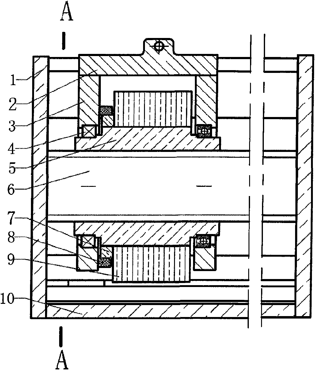
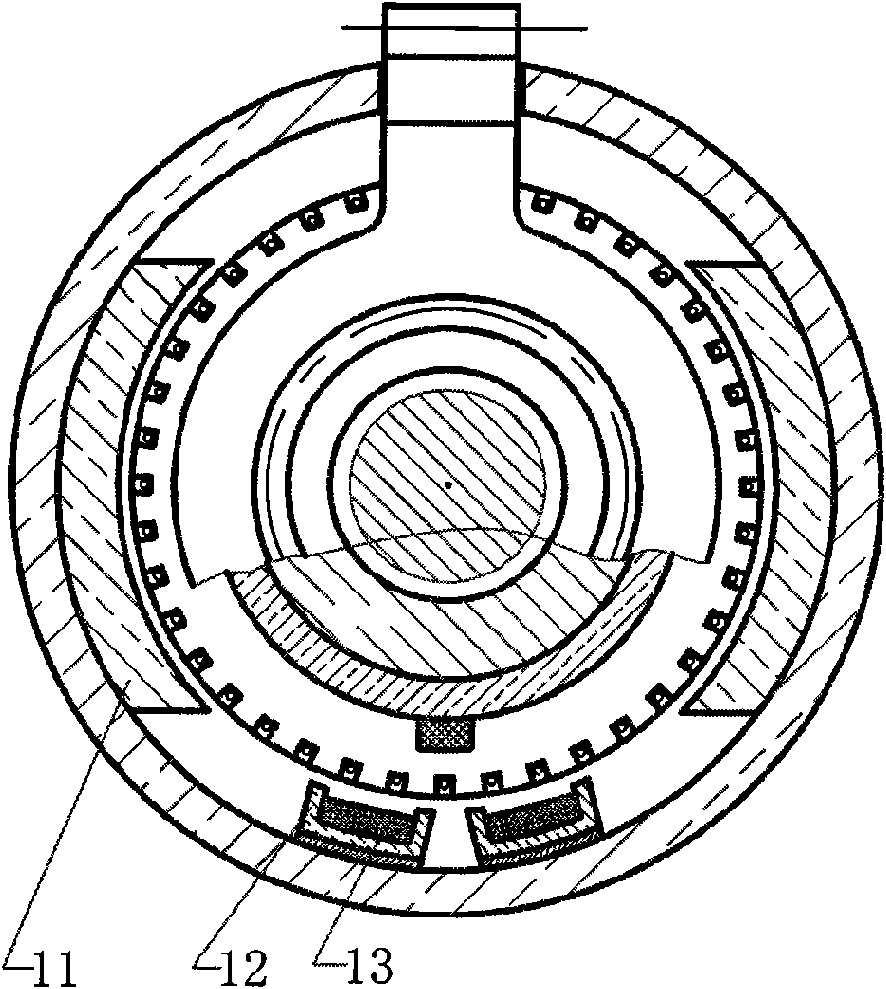
[0008] Below in conjunction with accompanying drawing and embodiment the patent of the present invention is described further.

[0009] In order to make the motor have higher efficiency, the stator adopts permanent magnet poles, and the rotor armature adopts a slide rail power supply method similar to that of an electric locomotive.

[0010] In the figure, the stator poles (11) are fixed on the housing (10). Armature (9) and commutator (7) are fixed on the nut (5) to form the rotor. The commutator brush (8) and the power supply brush (13) are both installed on the shift fork, and are responsible for supplying power to the armature (9). The power supply slide rail (12) is fixed on the housing. The end cover (1) is fixed on the housing (10), and the screw shaft (6) is fixed on the end cover (1). The shift fork (3) is fixed together with the shift fork beam (2). The shift fork beam (2) is located in the groove of the housing and can slide in the groove. It is responsible for e...


PUM


Abstract

A screw motor is a motor which can convert electric energy into linear motion mechanical energy and comprises a lengthened stator and a shell, the shell and the stator are provided with slots along the axial direction, a rotor is hollow and is not lengthened, the shaft of the rotor is a screw rod shaft fixed on the end cover of the motor shell, the rotor and the screw rod shaft are connected by threads, the two ends of the rotor are respectively provided with a bearing, the outer edges of the bearings are respectively provided with a shifting fork, the end parts of the two shifting forks are fixedly connected with a beam which is positioned in the slot of the motor shell and can linearly slide in the slot. The rotor can do spiral movement on the screw rod shaft under the action of electromagnetic force, and the shifting fork beam is driven to output power externally by the bearings and the shifting fork. The shifting fork beam plays the role of magnetic conduction while outputting power externally, thus guaranteeing the integrity of the part of the shell coupled with the rotor and a stator magnetic circuit. The screw motor has the advantages of being directly used as the power source for linear motion, and having higher acceleration and energy conversion efficiency.

Description

Technical field [0001] The patent of the present invention relates to a device for converting electrical energy into linear motion mechanical energy, and furthermore relates to a screw motor. Background technique [0002] At present, the existing motors are divided into rotary motors and linear motors according to the relative movement mode. The rotary motor has high efficiency and simple power supply control, but to generate linear power output, it is necessary to configure a device that converts rotary motion into linear motion, which increases the mass of the moving part of the entire device, reduces acceleration and efficiency, and when the motion distance is long This shortcoming is particularly obvious. The use of linear motors can save the mechanical device that converts rotary motion into linear motion, and directly output linear power. The system has small motion mass and high acceleration, but the efficiency of linear motors is low, and linear motors require compl...

Claims


Application Information

Patent Timeline
Patent Type & Authority Applications(China)
IPC IPC(8): H02K7/06H02K13/00
Inventor 杨士平
Owner 杨士平
Why Eureka
Try Eureka