
Method for establishing temporary supporting frame system assembled by steel structures

A temporary support and establishment method technology, applied in 3D modeling, image data processing, special data processing applications, etc., can solve problems such as difficult control of internal dimensions, irregular appearance, failure to meet construction requirements, etc., to achieve significant cost control, The effect of reducing construction auxiliary materials and improving predictability

Inactive Publication Date: 2013-04-03
WUHAN YIYE STEEL STRUCTURE
View PDF5 Cites 0 Cited by
  • Summary
  • Abstract
  • Description
  • Claims
  • Application Information

AI Technical Summary

Problems solved by technology

More and more novel space steel structure types appear, such as large-scale bending-torsion space box steel structure or pipe truss structure, the appearance contour control lines of its components are mostly irregular space polylines, and these curves have no fixed curves equation, and the direction of the included angles of different arcs is constantly changing. The surface of the component forms an irregular bending surface, the appearance is extremely irregular, and the internal size is difficult to control. The traditional construction method can no longer meet the construction requirements. It is necessary to establish an accurate and safe temporary support tire frame system with the support of computer three-dimensional simulation modeling technology, and a more reasonable and higher-precision assembly method

Method used


Image

  • Method for establishing temporary supporting frame system assembled by steel structures
  • Method for establishing temporary supporting frame system assembled by steel structures
  • Method for establishing temporary supporting frame system assembled by steel structures

Examples


Embodiment Construction

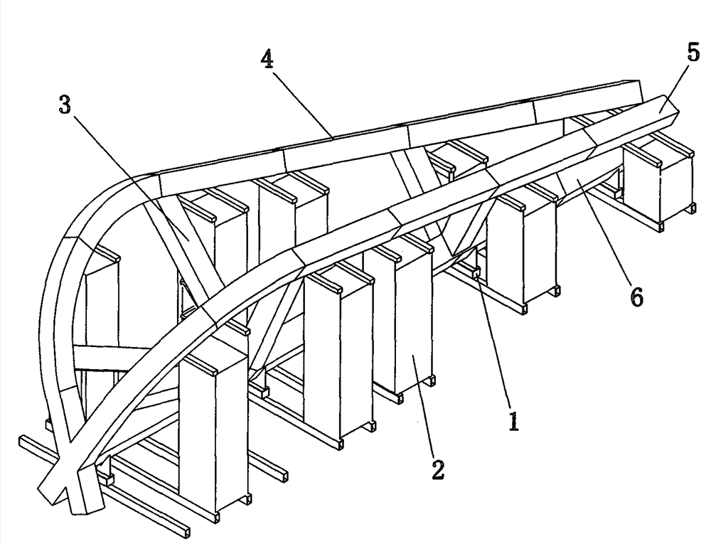
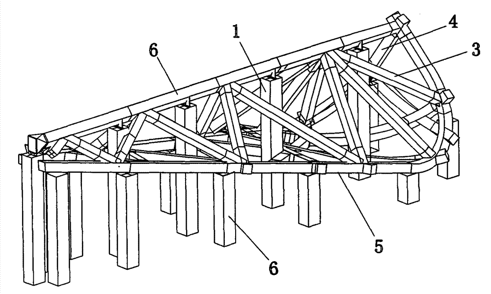
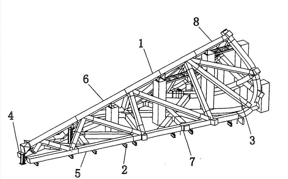
[0017] The invention provides a method for establishing a temporary support tire frame system for assembling large-scale steel structure building units. The method is: using computer three-dimensional modeling software to first establish a three-dimensional simulation of the large-scale steel structure that needs to be assembled. Model, and according to the simulation model to determine the assembly posture of the steel structure unit body and assembly segmentation; then according to the assembly posture optimization of the unit body to establish the assembly coordinate system, output the three-dimensional appearance control point of each characteristic appearance of the structure to be assembled under the assembly coordinate system Finally, according to the three-dimensional coordinate system and the assembly posture of the steel structure unit, a temporary support frame system that does not interfere with the unit members is designed.

[0018] The present invention adopts fol...


PUM


Abstract

The invention provides a method for establishing a temporary supporting frame system assembled by steel structures, comprising the following steps of: using a three-dimensional modeling software in a computer to establish a three-dimensional simulation model of assembly units required by a large steel structure, determining the assembly attitude and the assembly section of the units of the steel structure according to the simulation model, establishing an assembly coordinate system in an optimization way according to the assembly attitude of the units, outputting the three-dimensional coordinate of all characteristic appearance control points of the structure to be assembled under the assembly coordinate system, and finally designing the temporary supporting frame system which does not interfere to the unit components according to the three-dimensional coordinate system and the assembly attitude of the steel structure units. The method can solve the problems of difficult assembly and high controlling precision of large spatial steel structure, particularly the steel structure with complex spatial shape such as box-type bent-twisted shape, etc., reduces the height of the construction operation surface during the assembly construction, ensures the assembly precision, reduces the operation risk, improves the construction efficiency and the foreseeability and reduces the auxiliarymaterials for construction to the maximum degree.

Description

technical field [0001] The invention relates to the technical field of construction of a steel structure system in a large stadium space, in particular to a method for establishing a temporary support frame system for assembling a large steel structure building unit. Background technique [0002] With the development of the national economy, there is a strong demand for building more and larger buildings with large spaces and super-large spaces such as sports, leisure, exhibitions, airports, hangars, etc. This kind of building form is generally a space steel structure, and the structure type can be divided into grid frame (light steel), space truss (heavy steel) and so on. These buildings usually have the characteristics of large span, unique shape, complex stress and regional symbolic significance after completion. After the appearance of this new building type of space steel structure, some new construction methods were derived immediately. According to comprehensive fac...

Claims


Application Information

Patent Timeline
Patent Type & Authority Patents(China)
IPC IPC(8): G06F17/50G06T17/00G06T19/00
Inventor 刘进瞿国庆吴梦先曹仁
Owner WUHAN YIYE STEEL STRUCTURE
Learn More