Supercharge Your Innovation With Domain-Expert AI Agents!

Refractory system for bushing assembly

A technology for bushings and components, applied in manufacturing tools, glass manufacturing equipment, etc., can solve the problems of increasing downtime of fiber forming equipment, damage to bushings, and easy rupture of thermal insulation materials.

Inactive Publication Date: 2009-10-14
OCV INTELLECTUAL CAPITAL LLC
View PDF0 Cites 0 Cited by
  • Summary
  • Abstract
  • Description
  • Claims
  • Application Information

AI Technical Summary

Problems solved by technology

In particular, this insulation is prone to cracking and separation from the bushing and frame, leading to premature failure of the bushing
Additionally, the use of cast materials increases downtime for fiber forming equipment, as the insulation needs to set and cure, often taking days to cure

Method used


Image

  • Refractory system for bushing assembly
  • Refractory system for bushing assembly
  • Refractory system for bushing assembly

Examples


Embodiment Construction

[0016] As will be readily appreciated by those skilled in the art, the description herein generally includes a schematic illustration of one suitable manufacturing method for producing glass or mineral fibers.

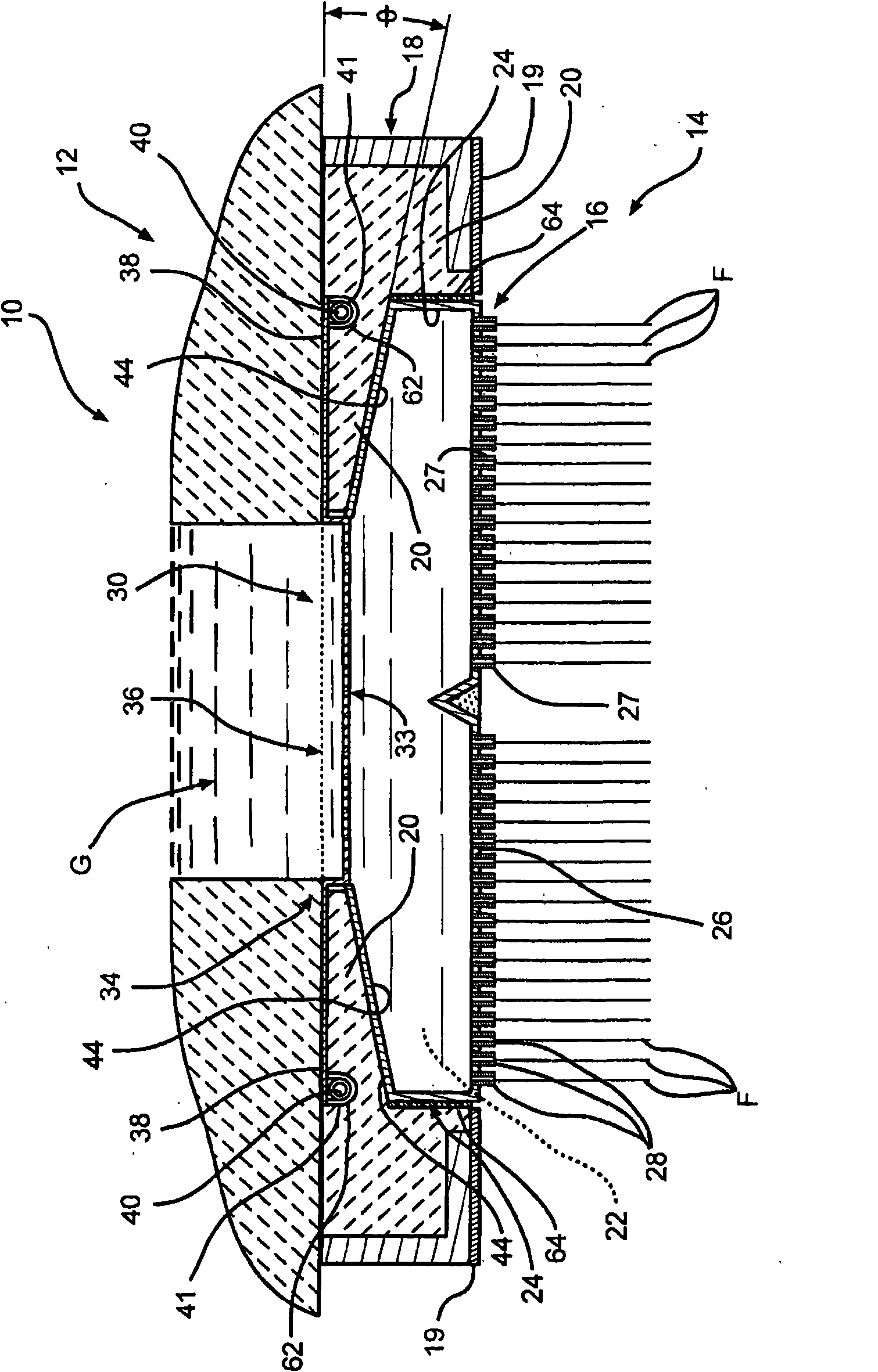
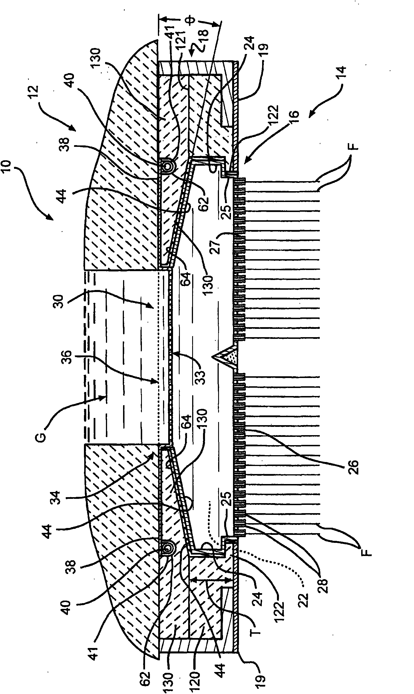
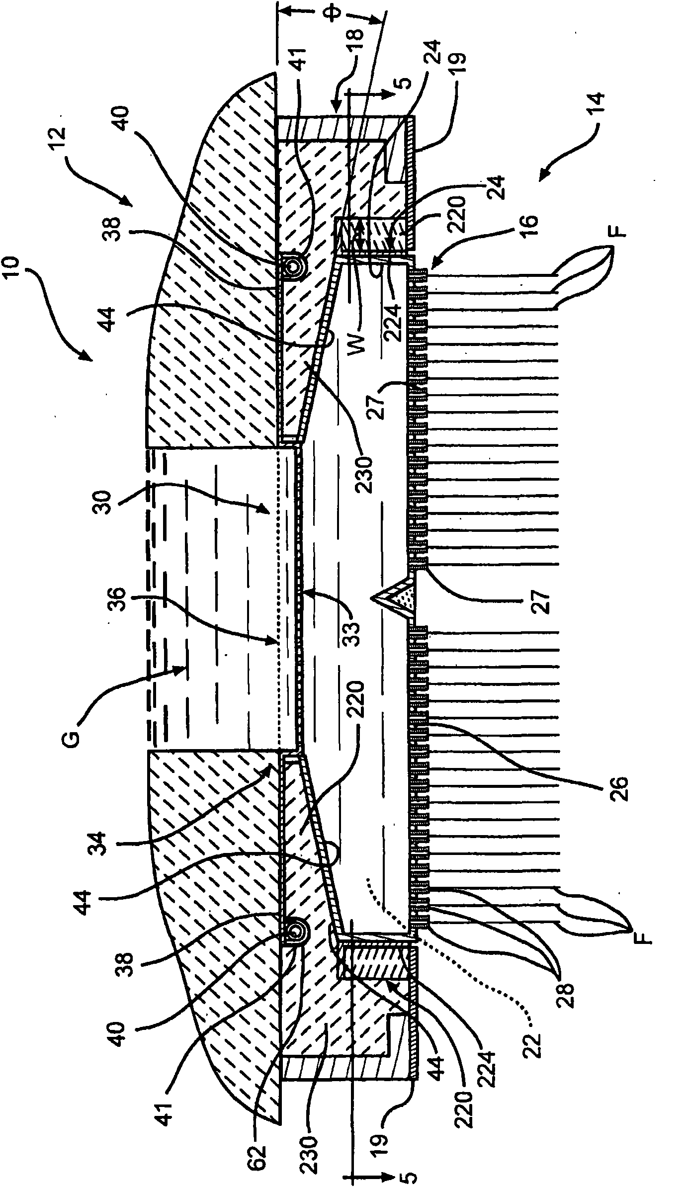
[0017] Referring now to the accompanying drawings, figure 1 One embodiment of a fiber forming assembly 10 comprising a breakout brick 12 and a breakout assembly 14 is shown. The bushing plate assembly 14 includes a bushing plate 16 and a frame 18 surrounding the bushing plate 16 . Bushing plate assembly 14 also includes a plurality of precast or sintered refractory material sections 20 disposed in the space between frame 18 and bushing plate 16, as in Figure 4 is schematically shown in , and will be further explained below.

[0018] The bushing 16 consists essentially of an electrically conductive material. In certain embodiments, bushing plate 16 takes the form of an elongated, generally rectangular metal box. Such as Figure 4 Shown schematically, the bushing p...


PUM


Abstract

A fiber forming bushing assembly includes a frame and a bushing within the frame. One or more sections formed of a pre-cast refractory material are positioned between at least a lower sidewall of the bushing and the frame.

Description

technical field [0001] The present invention relates generally to a heat resistant system for producing continuous filaments, and more particularly to bushing assemblies in filament forming equipment. The invention can be used in continuous glass filament and mineral fiber production. Background technique [0002] Bushings used in filament or fiber production have thin metal side walls, end walls and a bottom that form a heating chamber. The heating chamber is surrounded by thermal insulation. This bottom has the bushing orifices located therein, from where the molten material is attenuated to produce fibers. These walls and bottom are made of a noble metal (usually a platinum-based alloy) capable of withstanding the elevated bushing operating temperatures. The end walls of the bushings have electrical terminals or lugs between which current passes through the bushing walls, heating the bushing walls to operating temperature. [0003] During fiber forming operations, the...

Claims


Application Information

Patent Timeline
Patent Type & Authority Applications(China)
IPC IPC(8): C03B37/08
CPCC03B37/08
Inventor T·A·沙利文B·L·比米斯D·F·珀维斯
Owner OCV INTELLECTUAL CAPITAL LLC
Features
  • R&D
  • Intellectual Property
  • Life Sciences
  • Materials
  • Tech Scout
  • Unparalleled Data Quality
  • Higher Quality Content
  • 60% Fewer Hallucinations
Learn More