Hydraulic coupler type limited-slip differential

A technology of hydraulic coupling and anti-skid differential, which is applied in the direction of control devices, transportation and packaging, and vehicle parts, and can solve problems such as inapplicability to special road surfaces, poor car passability, and difficult steering of cars, and achieve increased Efficiency and flexibility, improved driving flexibility, low cost effect

Inactive Publication Date: 2009-10-21
熊涔博
View PDF0 Cites 4 Cited by
  • Summary
  • Abstract
  • Description
  • Claims
  • Application Information

AI Technical Summary

Problems solved by technology

[0002] The ordinary gear differentials currently used in various cars cannot be applied to special road surfaces, that is, when one wheel slips, the other wheel will not be able to obtain driving force and the car will not be able to move forward, and the trafficability of the car is not good. ; For the existing various anti-skid differentials, there are common defects such as complex operation, easy occurrence of damage to the half shaft due to excessive mechanical torque on a single half bearing, and difficulty in turning the car due to the relative rotation of the two half shafts.

Method used


Image

  • Hydraulic coupler type limited-slip differential
  • Hydraulic coupler type limited-slip differential
  • Hydraulic coupler type limited-slip differential

Examples


Embodiment Construction

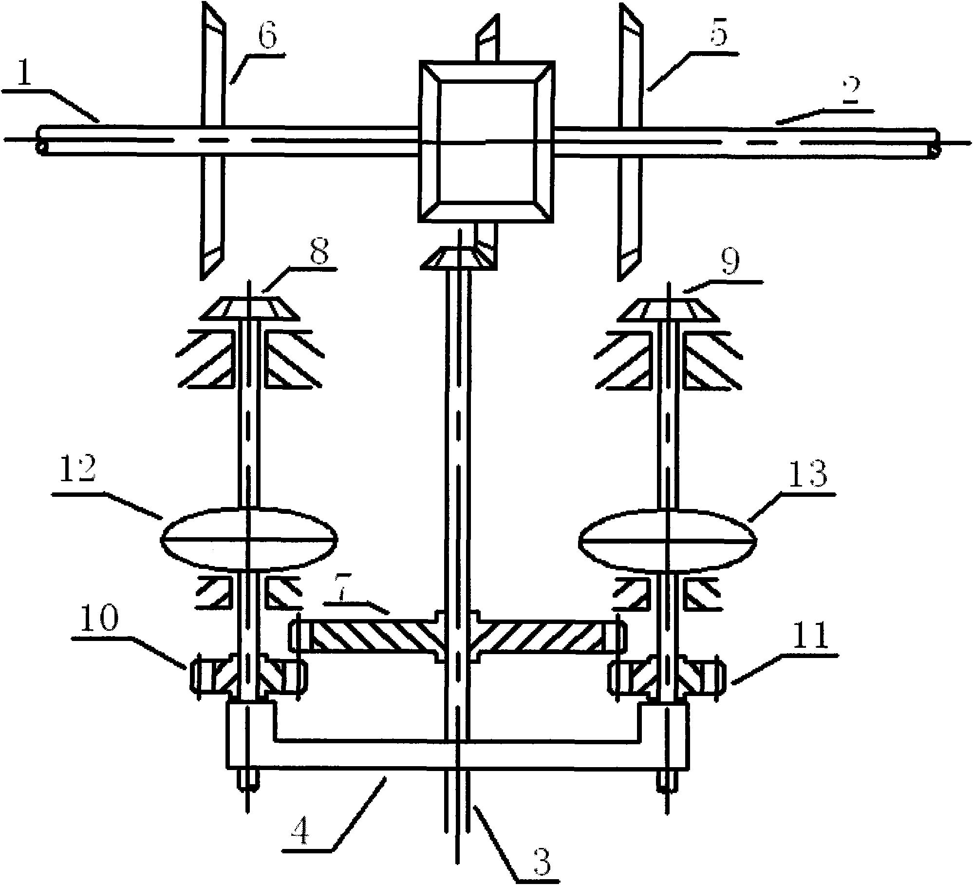
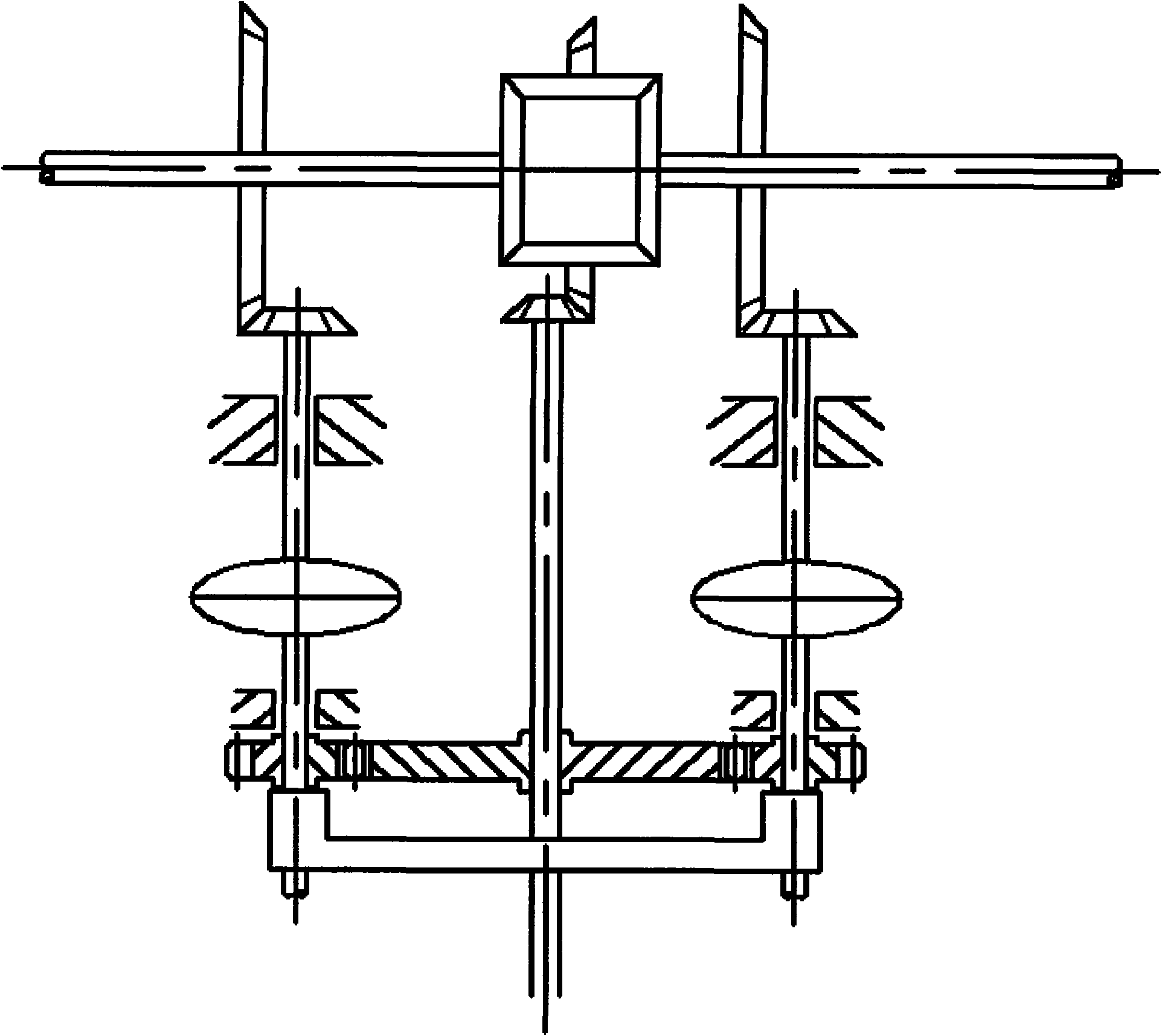
[0015] The structure and function of the present invention will be described below in conjunction with the drawings

[0016] see figure 1 , the left half shaft (2), the right half shaft (1) and the drive shaft (3) constitute a common gear differential.

[0017] Bevel gears (5) are fixed on the left half shaft (2), bevel gears (6) are fixed on the right half shaft (1), and gears (7) are fixed on the transmission shaft (3).

[0018] The coupling shaft of the hydraulic coupling is connected with the vehicle body through bearings, and the bevel gear (5) is usually disengaged from the bevel gear (9), bevel gear (6) and bevel gear (8) through the return spring, and the gear (7) disengage with gears (10), (11).

[0019] The gear shift slider (4) pushes the coupling shaft of the hydraulic coupling through the gear shift action, so that the bevel gear (5) and the bevel gear (9), the bevel gear (6) and the bevel gear (8), and the gear (7) and the gear (10), (11) enter meshing simulta...


PUM


Abstract

A hydraulic coupling type limited-slip differential has two gear functions, i.e. a common gear differential gear and a hydraulic coupler differential gear. The hydraulic coupling type limited-slip differential is in the common gear differential gear in a usual state, can develop the high efficiency of the common gear differential gear to carry out transmission under a better road condition and can shift gears under a poorer road condition so that the hydraulic coupler type limited-slip differential is in a work state of the transmission of a hydraulic coupler differential, thereby a transmission shaft can distribute more torques to a half shaft with a larger drag torque according to the torsion conditions of two half shafts; and in addition, the invention enhances the passing ability of an automobile by driving the automobile to go forwards.

Description

technical field [0001] The invention relates to a differential, which is suitable for automobiles and other equipment. Background technique [0002] The ordinary gear differentials currently used in various cars cannot be applied to special road surfaces, that is, when one wheel slips, the other wheel will not be able to obtain driving force and the car will not be able to move forward, and the trafficability of the car is not good. For existing various non-slip differentials, ubiquitous operation is complicated, easily occurs that single half-bearing is subjected to excessive mechanical torque and damages half-shaft and two half-shafts can not take place relative rotation and makes the defect such as the steering difficulty of automobile. [0003] Off-road vehicles, trucks and some passenger cars driving on poor road conditions have an even more urgent demand for high-performance limited slip differentials. Contents of the invention [0004] The purpose of the present in...

Claims


Application Information

Patent Timeline
Patent Type & Authority Applications(China)
IPC IPC(8): B60K17/16
Inventor 熊涔博
Owner 熊涔博
Why Eureka
Try Eureka