

Diaphragm for speaker, frame for speaker, dust cap for speaker, speaker and apparatus using them, and method for manufacturing component for speaker
A manufacturing method and speaker technology, applied in the field of devices, to achieve the effects of improving water resistance reliability, high elastic modulus, and preventing secondary agglomeration
- Summary
- Abstract
- Description
- Claims
- Application Information
AI Technical Summary
Problems solved by technology
Method used
Image

Examples
Embodiment approach 1
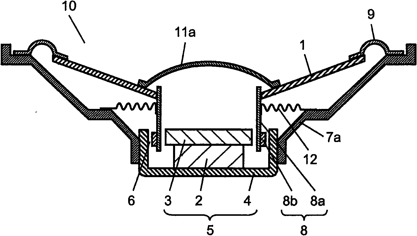
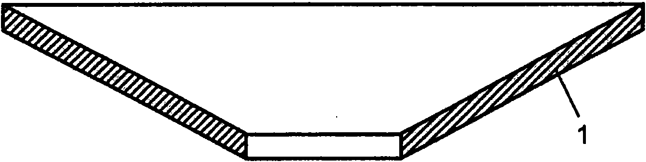
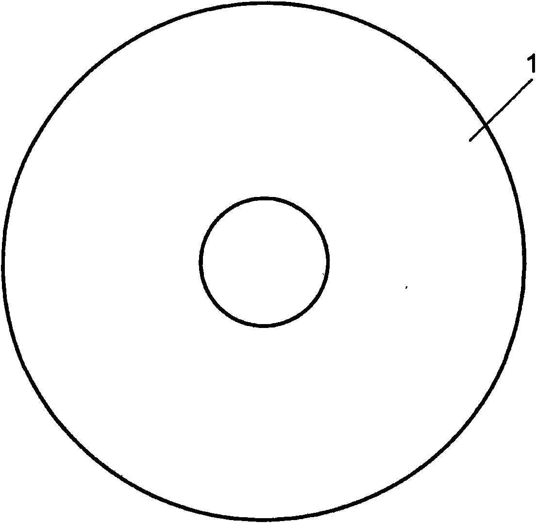
[0101] Next, use figure 1 ˜ FIG. 4 describe Embodiment 1 of the present invention. figure 1 It is a cross-sectional view of speaker 10 in Embodiment 1 of the present invention. figure 2 is used for figure 1 The illustrated speaker 10 is a cross-sectional view of a speaker diaphragm 1 (hereinafter, referred to as a diaphragm 1 ). image 3 yes figure 2 A top view of the vibrating plate 1 is shown. Figure 4A yes figure 2 A partially detailed cross-sectional view of the vibrating plate 1 is shown. Figure 4B is used for figure 1 The partial detailed cross-sectional view of the loudspeaker diaphragm 1 which is another form of the loudspeaker 10 shown.
[0102] Such as figure 1 As shown, speaker 10 has diaphragm 1 , magnetic circuit 5 , speaker housing 7 a (hereinafter referred to as housing 7 a ), and voice coil 8 . The magnetic circuit 5 is formed by sandwiching the magnetized magnet 2 between the upper clamp 3 and the yoke 4 . The frame body 7 a is connected to...
Embodiment approach 2
[0145] Next, Embodiment 2 of the present invention will be described using the drawings. In addition, the same reference numerals are assigned to the same configuration as in the first embodiment, and detailed description thereof will be omitted.
[0146] Figure 5 It is a cross-sectional view of speaker 10a in Embodiment 2 of the present invention. Image 6 is used for Figure 5 The shown speaker 10a is a cross-sectional view of a speaker housing 7 (hereinafter referred to as housing 7). Figure 7 yes Image 6 A partially detailed cross-sectional view of frame 7 is shown.
[0147] Compared with the speaker 10 in the first embodiment, the speaker 10a in the second embodiment replaces the diaphragm 1 in the first embodiment with a speaker diaphragm 1a (hereinafter referred to as a diaphragm 1a), and replaces the frame body 7a with a frame. body7. Other configurations of the speaker 10a of the second embodiment are the same as those of the speaker 10 of the first embodimen...
Embodiment approach 3
[0177] Next, Embodiment 3 of the present invention will be described using the drawings. In addition, the same code|symbol is attached|subjected to the same structure as Embodiment 1, 2, and detailed description is abbreviate|omitted.
[0178] Figure 8 It is a cross-sectional view of speaker 10b in Embodiment 3 of the present invention. Figure 9 is used for Figure 8 A cross-sectional view of a speaker dustproof cover 11 (hereinafter, referred to as a cover 11 ) of the speaker 10b shown. Figure 10 yes Figure 9 A partially detailed cross-sectional view of cover 11 is shown.
[0179] Compared with speaker 10 in Embodiment 1, speaker 10 b in Embodiment 3 has diaphragm 1 in Embodiment 1 replaced with diaphragm 1 a and cover 11 a replaced with cover 11 . Other configurations of the speaker 10b of the third embodiment are the same as those of the speaker 10 of the first embodiment. Furthermore, in the speaker 10b in Embodiment 3, compared with the speaker 10a in Embodiment...
PUM
| Property | Measurement | Unit |
|---|---|---|
| Length | aaaaa | aaaaa |
| Average fiber diameter | aaaaa | aaaaa |
| Fiber length | aaaaa | aaaaa |
Abstract
Description
Claims
Application Information