Eureka AIR delivers breakthrough ideas for toughest innovation challenges, trusted by R&D personnel around the world.

Power generation device capable of collecting wind in many directions

A power generation device and wind collection technology, applied in wind power generation, renewable energy power generation, wind turbines at right angles to the wind direction, etc., can solve the problems of bulky, general products without suitable structure, large size, etc.

Active Publication Date: 2009-10-28
林碧霞
View PDF0 Cites 9 Cited by
  • Summary
  • Abstract
  • Description
  • Claims
  • Application Information

AI Technical Summary

Problems solved by technology

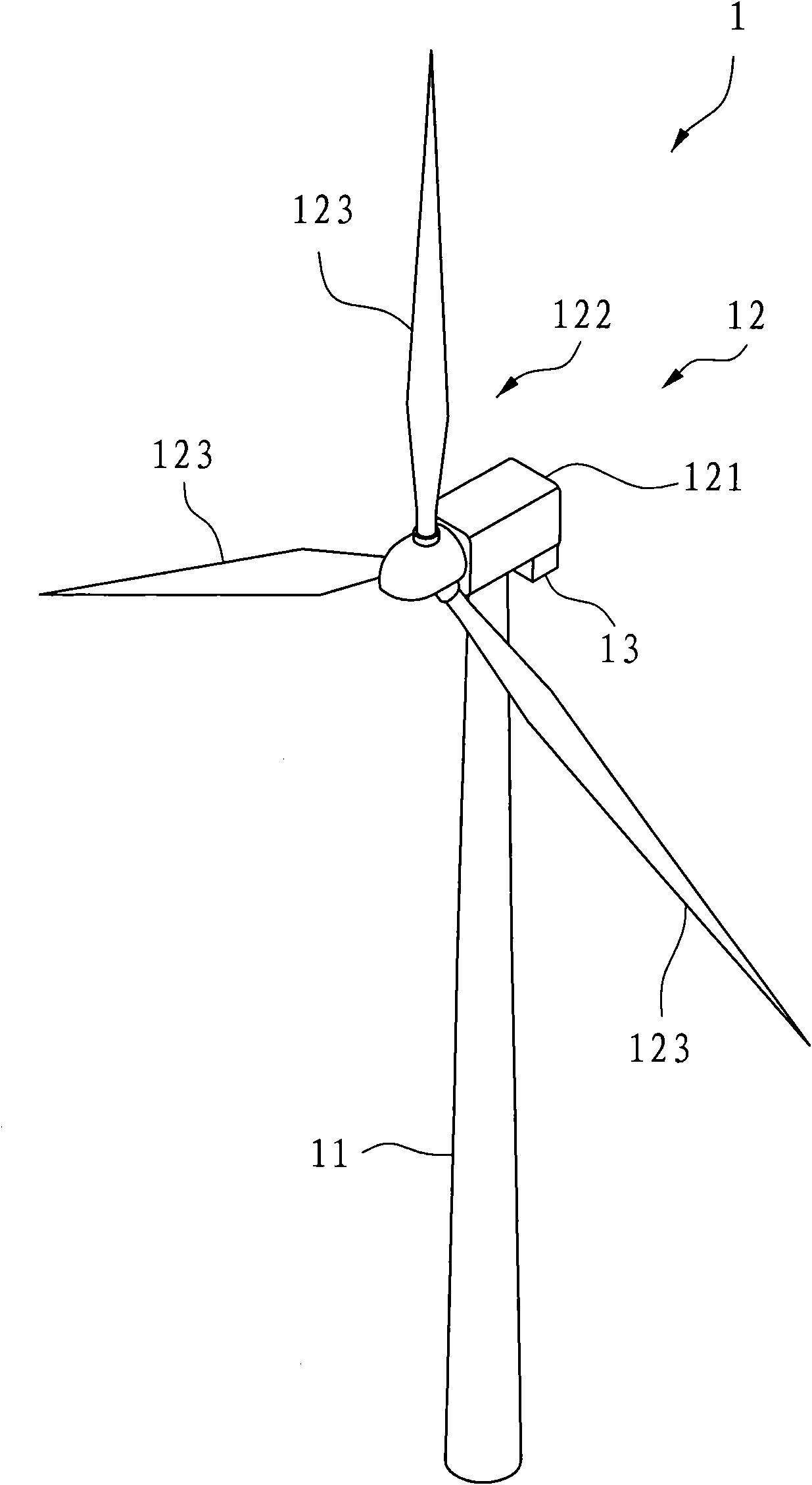
[0006] 1. Large volume: the center of the body 121 of the fan 12 of the existing wind power generation device 1 is about 70 meters (m, meter) from the ground, and the length of each fan blade 123 is about 70 meters (m, meter). It can be seen from this that the overall volume of the existing wind power generating device 1 is too large and can only be installed in a relatively open place. For cities with many tall buildings, the existing wind power generating device 1 is all relatively inconvenient to install and use.
[0007] 2. Unstable power generation efficiency: the main body 121 of the fan 12 of the existing wind power generation device 1 is fixed on the support frame 11, thereby increasing the structural stability. However, the wind direction is changeable, so it is fixed on the support The main body 121 of the fan 12 on the frame 11 cannot change direction with the wind field, and can only generate electricity by receiving the wind blowing in a fixed direction, so that the fan blade 123 cannot be blown by the wind at any time to rotate, resulting in unstable power generation efficiency
[0008] This shows that above-mentioned existing wind power generation device obviously still has inconvenience and defect in structure and use, and urgently needs to be further improved
In order to solve the above-mentioned problems, the relevant manufacturers have tried their best to find a solution, but for a long time no suitable design has been developed, and the general product has no suitable structure to solve the above-mentioned problems. This is obviously the relevant industry. Urgent problem

Method used


Image

  • Power generation device capable of collecting wind in many directions
  • Power generation device capable of collecting wind in many directions
  • Power generation device capable of collecting wind in many directions

Examples


Embodiment Construction

[0038] In order to further explain the technical means and effects of the present invention to achieve the intended purpose of the invention, the specific implementation, structure, Features and their functions are described in detail below.

[0039] The aforementioned and other technical contents, features and effects of the present invention will be clearly presented in the following detailed description of preferred embodiments with reference to the drawings. Through the description of the specific implementation mode, when the technical means and functions adopted by the present invention to achieve the predetermined purpose can be obtained a deeper and more specific understanding, but the accompanying drawings are only for reference and description, and are not used to explain the present invention be restricted. Before the present invention is described in detail, it is noted that in the following description, similar elements are denoted by the same numerals.

[0040]...


PUM


Abstract

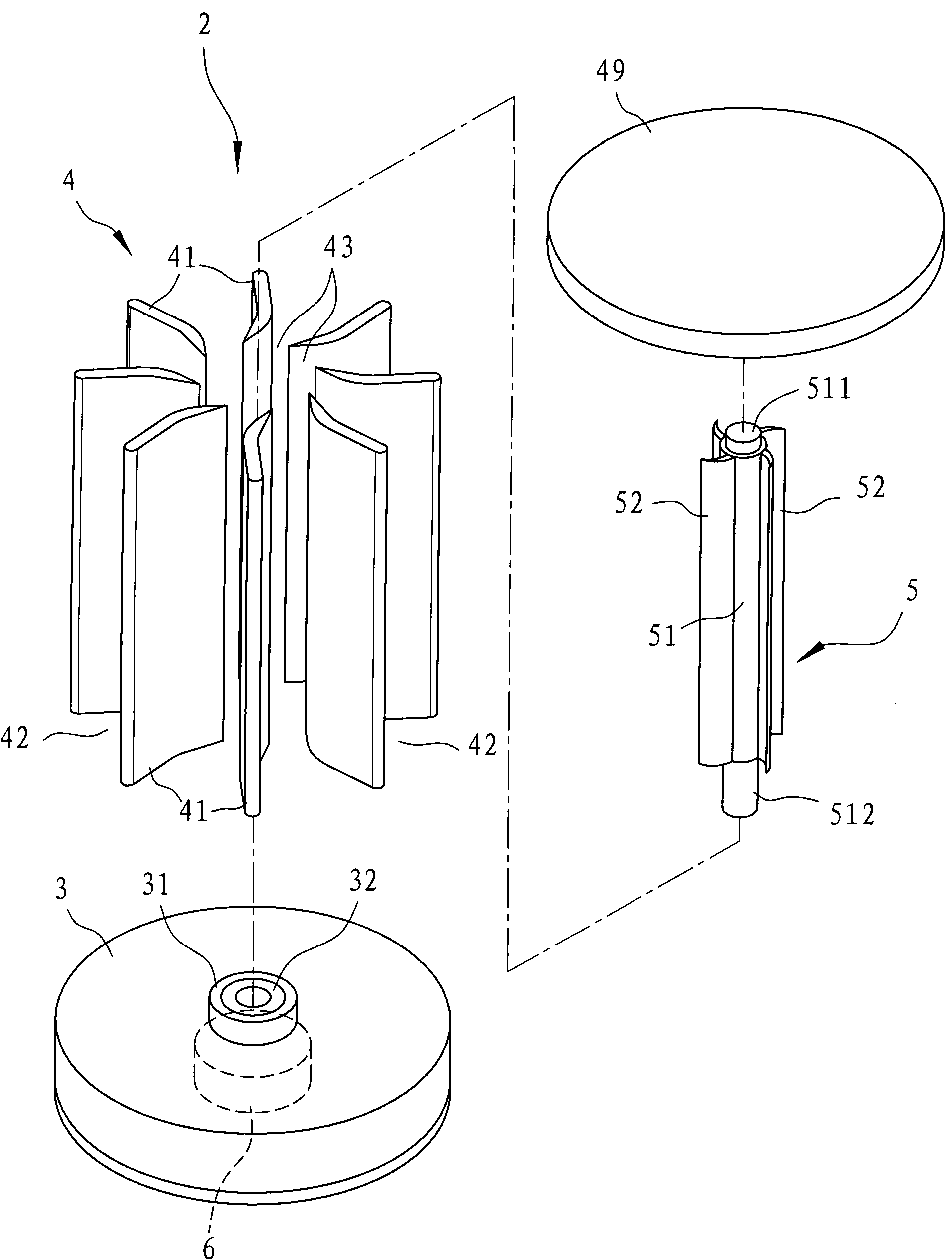
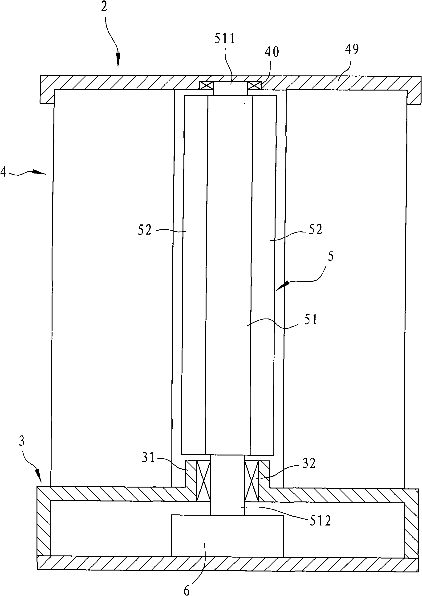
The invention relates to a power generation device capable of collecting wind in many directions, which comprises a base, a power generation unit arranged in the base, a rotating unit and a wind collecting unit which is arranged on the base and surrounds the rotating unit, wherein the wind collecting unit comprises a plurality of vertical wind collecting plates which are arranged radially at intervals; the outer edges of two adjacent wind collecting plates are matched with each other to form a wind inlet, and the inner edges of two adjacent wind collecting plates are matched with each other to form a wind collecting port; and the rotating unit is provided with a rotating shaft and a plurality of vanes, wherein the rotating shaft can be driven to rotate by wind force to drive the power generation unit, and the vanes extend outwards from the rotating shaft. When the wind collecting unit is blown by wind force from different directions, the wind can be introduced from the wind inlet corresponding to the wind direction to collect the wind force, and thus, the vanes of the rotating unit can be continuously blown by the wind force to stabilize the benefit of wind power generation.

Description

technical field [0001] The invention relates to a power generation device, in particular to a power generation device capable of collecting wind from multiple directions with small volume and stable power generation efficiency. Background technique [0002] Today, when the earth's available resources are becoming increasingly scarce and environmental protection awareness is increasing, due to the characteristics of clean renewable energy and low greenhouse gas emissions, the utilization and development of renewable energy are increasingly valued by countries. Among them, solar power and wind power are the most important. valued. [0003] see figure 1 Shown is a perspective view of an aspect of a conventional wind power plant. The existing wind power generation device 1 includes a support frame 11 fixed at one end on the ground, a fan 12 fixed at the other end of the support frame 11 , and a generator set 13 electrically connected with the fan 12 . [0004] The fan 12 has ...

Claims


Application Information

Patent Timeline
IPC IPC(8): F03D3/04F03D3/06F03D9/00F03D9/25
CPCY02E10/72Y02E10/74
Inventor 钟俊能
Owner 林碧霞
Why Eureka
Eureka Blog
Learn More