
Solar energy spike synchronization control method

A synchronous control, solar energy technology, applied in energy-saving control technology, synchronization, traffic control system of road vehicles, etc., can solve the problem of inability to apply long-distance marking enhancement, achieve simple and convenient implementation, reliable control, and overcome the limitation of area size Effect

Inactive Publication Date: 2009-10-28
陈卫
View PDF1 Cites 17 Cited by
  • Summary
  • Abstract
  • Description
  • Claims
  • Application Information

AI Technical Summary

Problems solved by technology

This application uses a wireless control method to realize the synchronization of discrete solar road studs. However, this wireless control method is the same as the wired control method. Due to the limitation of the control distance, it can only realize the synchronization and numerical control work of short-distance solar road studs in a small area. To adapt to the change of the lane running direction of the day and night lanes at each time period and the change of the direction of the variable lane at the intersection, the wireless control mode of synchronous operation of solar road studs is the same as the wired control mode, which cannot be applied to long-distance marking reinforcement, and will also be restricted Implementation cost of simultaneous control and operating cost of control management

Method used


Image

  • Solar energy spike synchronization control method

Examples


Embodiment

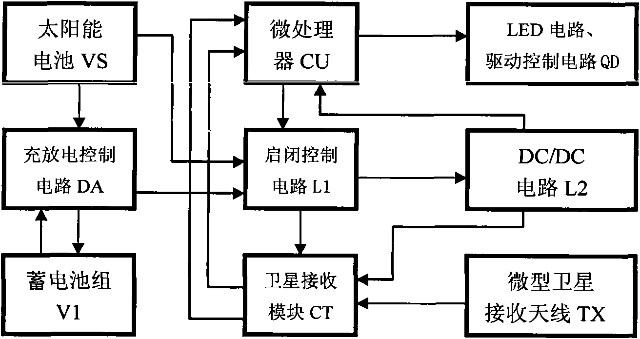
[0015] The control flow of the solar road stud synchronous control method of the embodiment is:

[0016] 1. The solar battery VS controls the charging or discharging of the built-in micro battery pack V1 through the charge and discharge control circuit DA, and controls the power supply of the electroluminescent device to be turned on or off through the charge and discharge control circuit V1;

[0017] 2. The micro-satellite receiving antenna TX receives the satellite timing signal provided by the timing function of the geosynchronous positioning satellite;

[0018] 3. When the micro-satellite receiving antenna TX receives the satellite timing signal, the satellite receiving module CT analyzes and extracts the time information and second synchronization information;

[0019] 4. After receiving the second synchronization signal provided by the satellite receiving module CT, the microprocessor CU turns on and off the electroluminescent devices of the discretely installed solar sy...


PUM


Abstract

The invention discloses a solar energy spike synchronization control method that uses the time service function of a geosynchronous positioning satellite, the solar energy synchronization spikes and the same time source to conduct synchronous working control on the solar energy synchronization spikes installed discretely. The solar energy synchronization spike comprises a shell, a solar cell, an accumulator battery, a charge-discharge on-off control circuit, a miniature satellite receiving antenna, a satellite receiving module, a microprocessor and an electroluminescent device. After receiving a time service signal of the geosynchronous positioning satellite, the miniature satellite receiving antenna analyzes and extracts time information and second synchronizing information through the satellite receiving module. After receiving a second synchronizing signal offered by the satellite receiving module, the microprocessor controls the synchronous turn-on and turn-off of the electroluminescent device according to preset flicker frequency and flicker duty ratio. Using synchronizing time to conduct synchronous working control on the solar energy spikes, the control method is not limited by factors such as the length and trend of roads, and is simple and convenient in implementation and reliable in control.

Description

technical field [0001] The invention relates to a method for controlling road studs, in particular to a synchronous control method for solar-powered road studs, which is mainly used in the enhanced display of marking lines in road traffic at night, and uses satellite timing to synchronously control the synchronous work of solar-powered road studs. Background technique [0002] Solar road studs are mainly used in dangerous roads where traffic accidents are frequent, such as expressway markings and cliff road markings, as a strengthening indicator of road direction at night, and in recent years in the fields of urban road beautification at night. The above applications require the solar road studs installed discretely along the road markings to work synchronously. In the asynchronous working state, it will produce a "dazzling" feeling and affect the safety of road traffic. Discretely installed solar road studs work synchronously. The technical solution adopted in the prior art...

Claims


Application Information

Patent Timeline
Patent Type & Authority Applications(China)
IPC IPC(8): G08G1/095H05B37/02G04G7/00G01S5/02
CPCY02B20/42H05B37/0281H05B37/02H05B47/16H05B47/165Y02B20/40
Inventor 陈伟
Owner 陈卫
Learn More