
Motor control method using space vector pulse width modulation and controller thereof

A technology of space vector pulse width and motor control, which is applied in the direction of vector control system, motor generator control, electromechanical brake control, etc. It can solve the problems of shortening vector time, increasing vector time, reducing the maximum speed and acceleration of the motor, etc., to achieve improvement Effect of effective vector time, maximum velocity and acceleration increase, decrease impact

Inactive Publication Date: 2009-10-28
SHANGHAI POWERMAX TECH INC
View PDF0 Cites 9 Cited by
  • Summary
  • Abstract
  • Description
  • Claims
  • Application Information

AI Technical Summary

Problems solved by technology

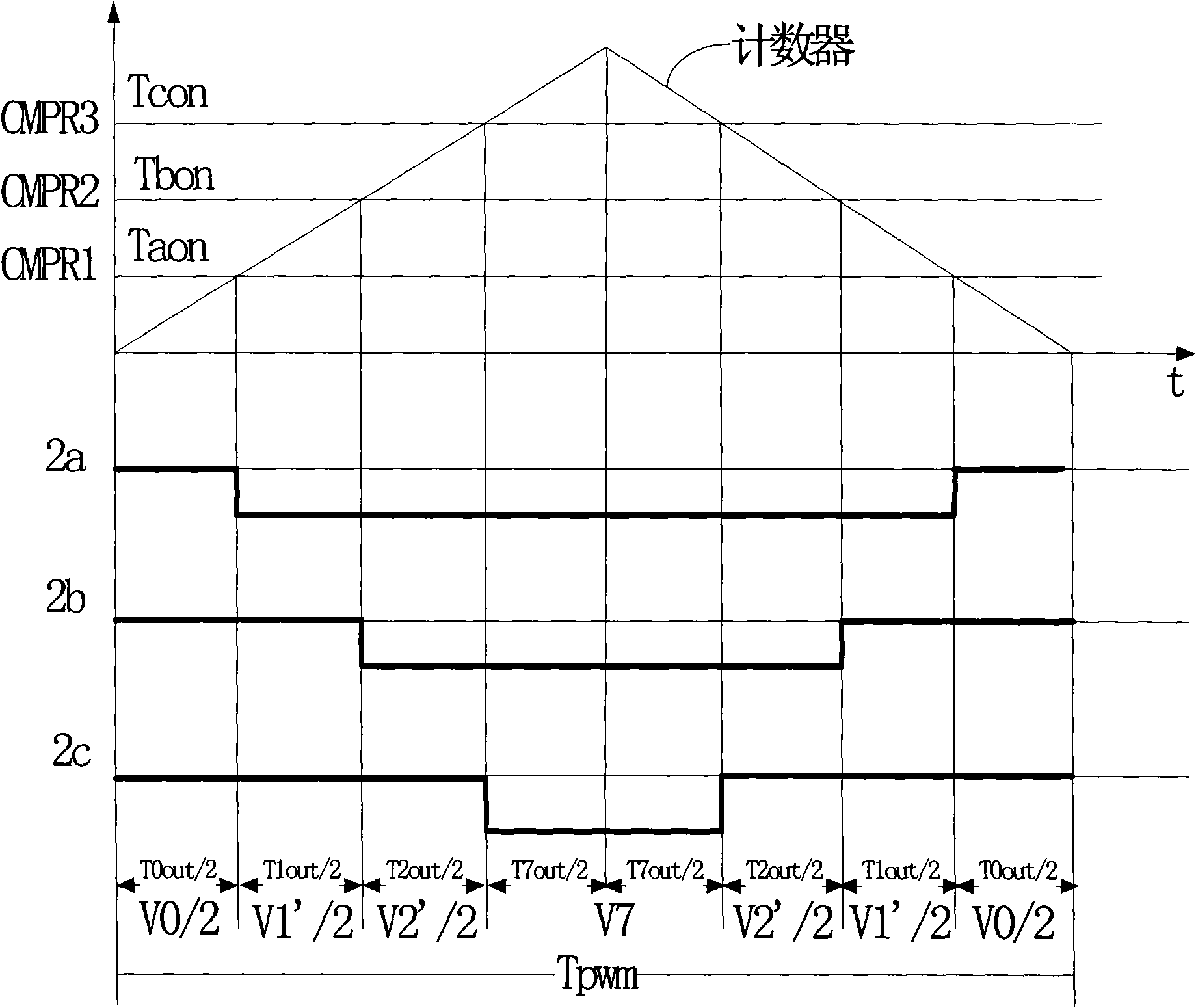
The problem with this method is that the current detection module of the lower arm of the inverter bridge collects the current value of the corresponding lower arm, while the space vector algorithm needs to collect the phase current of the motor; and the current sampling also takes time, so the state of V0 needs to be controlled The shortest time, and choose the appropriate sampling trigger time
In a PWM cycle, the increase of V0 voltage vector time will relatively shorten the V1', V2' voltage vector time, thereby reducing the maximum speed and acceleration of the motor

Method used


Image

  • Motor control method using space vector pulse width modulation and controller thereof
  • Motor control method using space vector pulse width modulation and controller thereof
  • Motor control method using space vector pulse width modulation and controller thereof

Examples


Embodiment Construction

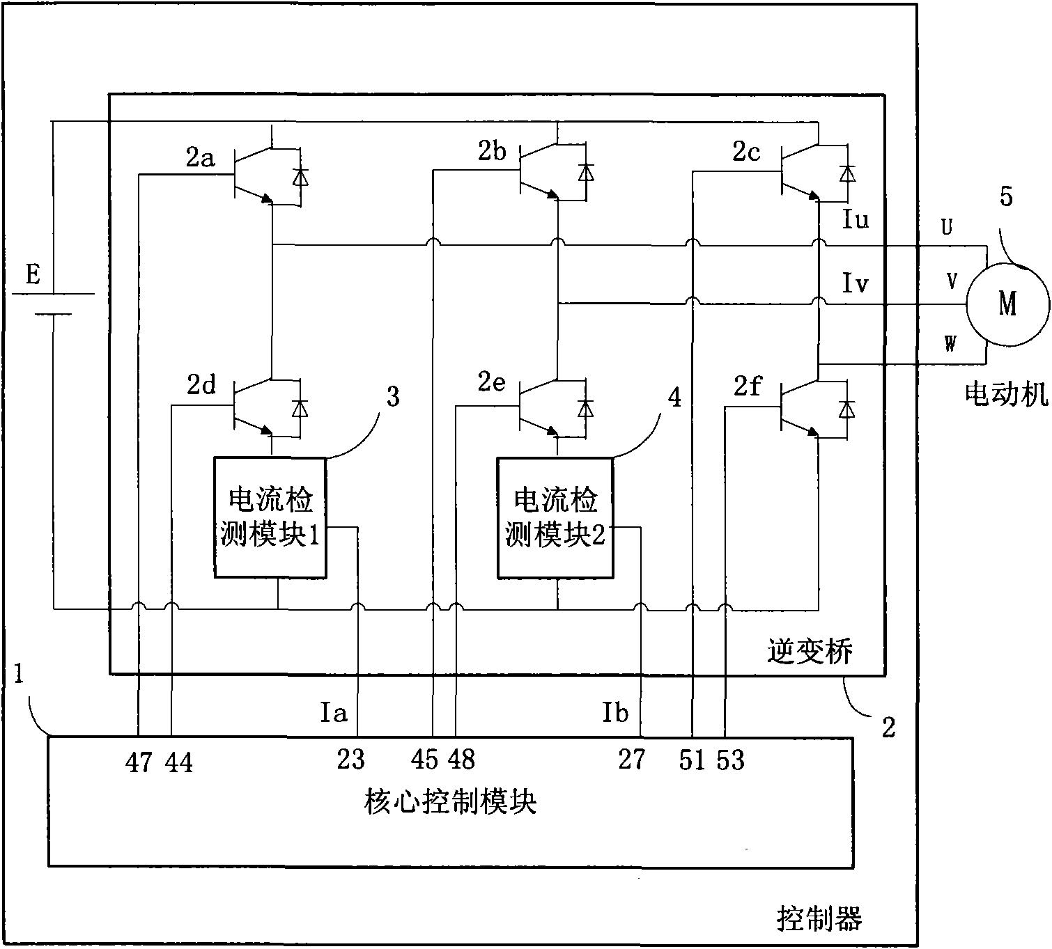
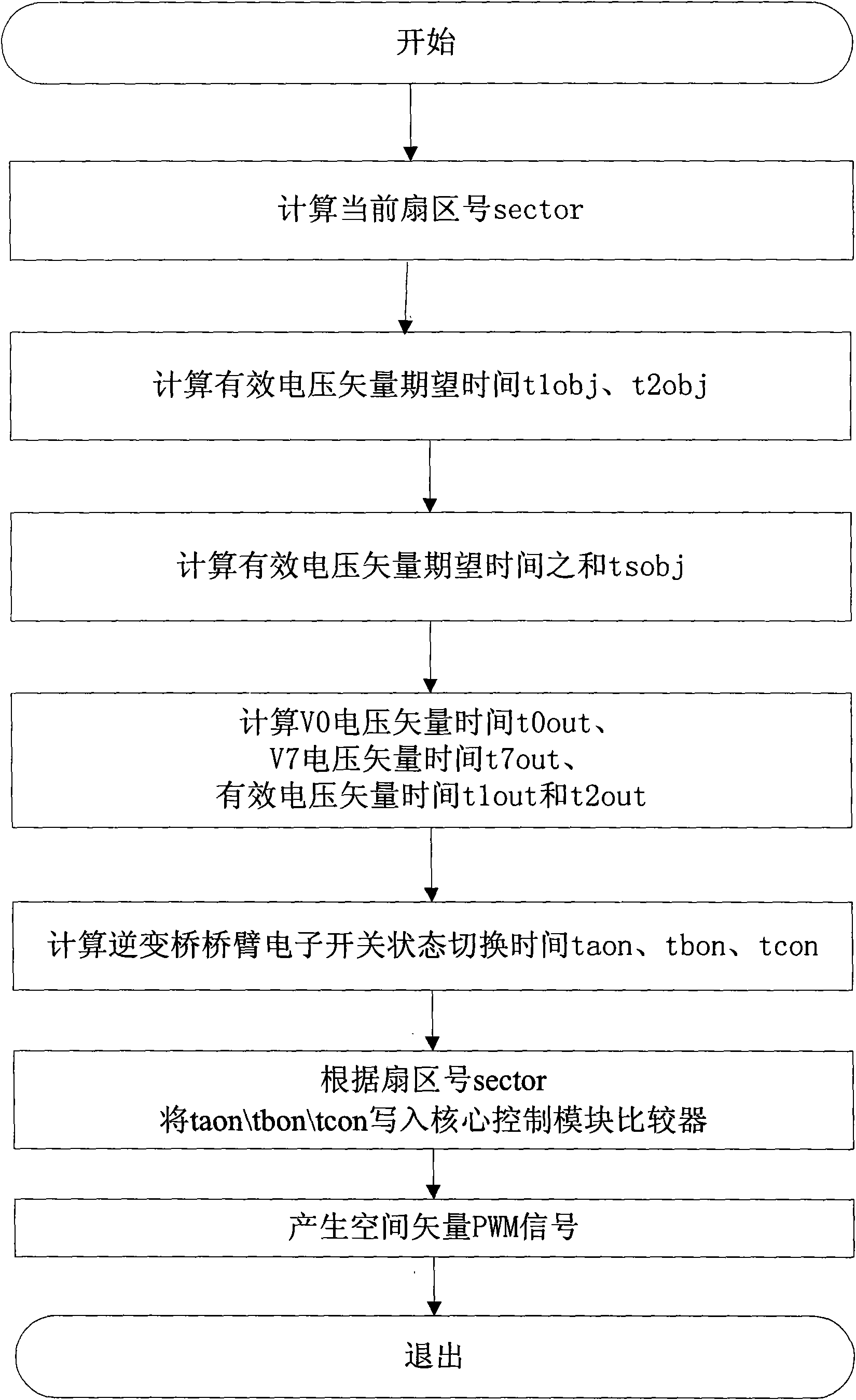
[0049] Such as figure 2 As shown, the present invention adopts the motor control method of space vector pulse width modulation, comprises core control module 1, the inverter bridge 2 that connects described core control module 1 and the motor 5 that connects inverter bridge 2, and this method comprises the following steps:

[0050] Step 1, current sampling step: when the inverter bridge 2 is in the V0 state, collect the output signals of the current detection modules 3 and 4 in the electronic switches 2d and 2e connected in series to the lower bridge arms of the inverter bridge 2, and output the current detection modules respectively 3 and 4 current signals Ia and Ib, the current signals Ia and Ib are proportional to the 5-phase current of the motor, and the acquisition time length is tad. The state of the switch is fully open;

[0051] Step 2, current control step: the core control module 1 receives the current signals Ia and Ib, transforms them through Clark and Park, comp...


PUM


Abstract

The invention discloses a motor control method using space vector pulse width modulation and a controller thereof. The method comprises the steps that an output signal of a current detecting module connected in series with a lower bridge arm electronic switch of an inverse bridge is collected when the inverse bridge is in a V0 state; beginning time sampled by a triggering current is controlled tocause the sampling process to be in the V0 period and cause the sampled current signals Ia and Ib to be in positive proportion to a motor phase current when V0 voltage vector time t0out for outputtinga space vector PWM signal is more than the minimum value t0min of the V0 voltage vector time; the V7 time t7out is controlled to be less than V0 time t0out when the V0 time is less than t0min duringthe partial modulation to compensate the V0 time so that the V7 time t7out is more than t0min, and the effective voltage vector time t1out and the effective voltage vector time t2out are relatively prolonged so as to improve the motor acceleration and the highest speed. The motor controller using the method has lower current detection hardware cost, can stabilize the phase current of the detectingmotor and simultaneously reduce or eliminate the influence on the motor acceleration and the highest speed due to current sampling as much as possible.

Description

technical field [0001] The invention relates to a motor control method and a controller thereof, in particular to a control method and a controller thereof for sampling a current signal of a lower bridge arm of an inverter bridge to generate a space vector pulse width modulation signal to drive a motor. Background technique [0002] In motor control technology, a common motor controller includes an isolated current detection module, a core control module and an inverter bridge. [0003] The isolated current detection module is installed at the phase line of the motor, which converts the phase current signal of the motor into a proportional signal output by means of isolation; for example, a Hall current sensor. [0004] The core control module accepts the current signal of the current detection module and outputs the space vector pulse width modulation signal to the electronic switch of the inverter bridge to control the operation of the motor; for example, the C2000 series ...

Claims


Application Information

Patent Timeline
IPC IPC(8): H02P6/00H02P6/08H02P6/16H02P21/00H02P21/22
Inventor 甄力黄麟刘革兴秦仓法
Owner SHANGHAI POWERMAX TECH INC
Learn More