
Rotational-free panoramic photography device and monitoring system comprising same

A panoramic camera and monitoring system technology, applied in closed-circuit television systems, TV system components, image communication, etc., can solve the problems of increasing the difficulty of equipment installation and wiring, save the cost of separate wiring, improve flexibility and applicability , The effect of reducing wiring costs

Active Publication Date: 2011-01-19
ZTE CORP
View PDF0 Cites 0 Cited by
  • Summary
  • Abstract
  • Description
  • Claims
  • Application Information

AI Technical Summary

Problems solved by technology

[0005] In the actual use of security equipment, there are still cases where each camera is connected to the monitor separately, which increases the difficulty of equipment installation and wiring

Method used


Image

  • Rotational-free panoramic photography device and monitoring system comprising same
  • Rotational-free panoramic photography device and monitoring system comprising same
  • Rotational-free panoramic photography device and monitoring system comprising same

Examples


Embodiment Construction

[0035] In order to further explain the technical means and effects that the present invention adopts to achieve the intended purpose, below in conjunction with the accompanying drawings and preferred embodiments, the non-rotating panoramic camera device and the monitoring system composed of it according to the present invention will be described in detail as follows: .

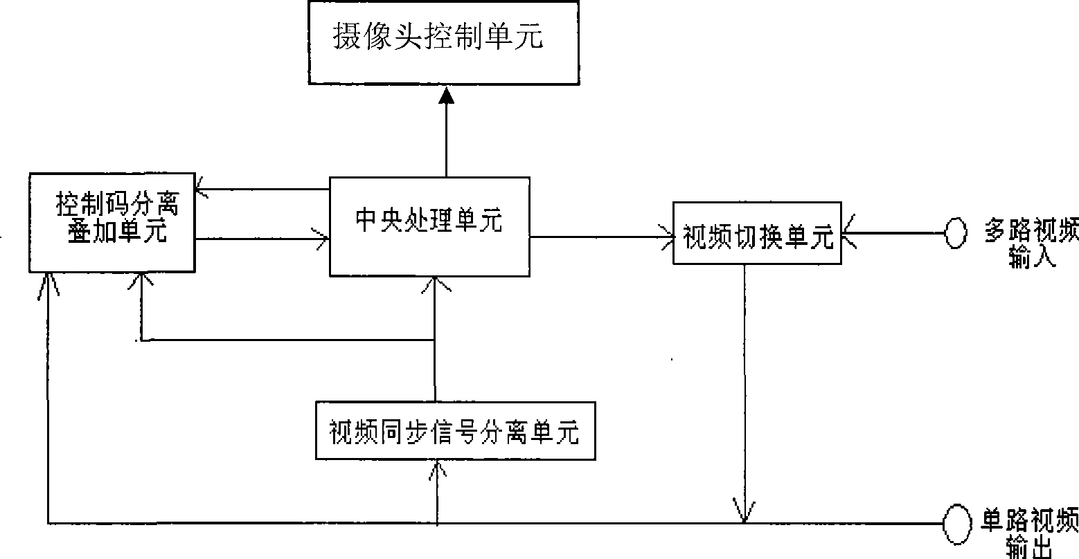
[0036] In the first embodiment, the basic functional principle diagram of the non-rotation panoramic camera device of the present invention is as follows: figure 2 shown. The non-rotating panoramic camera device in this embodiment includes a video switching unit, a central processing unit, a video synchronization signal separation unit, a control code separation and superimposition unit, a camera control unit and a camera. If infrared light-emitting diodes are installed on the camera, panoramic shooting at night can also be realized.

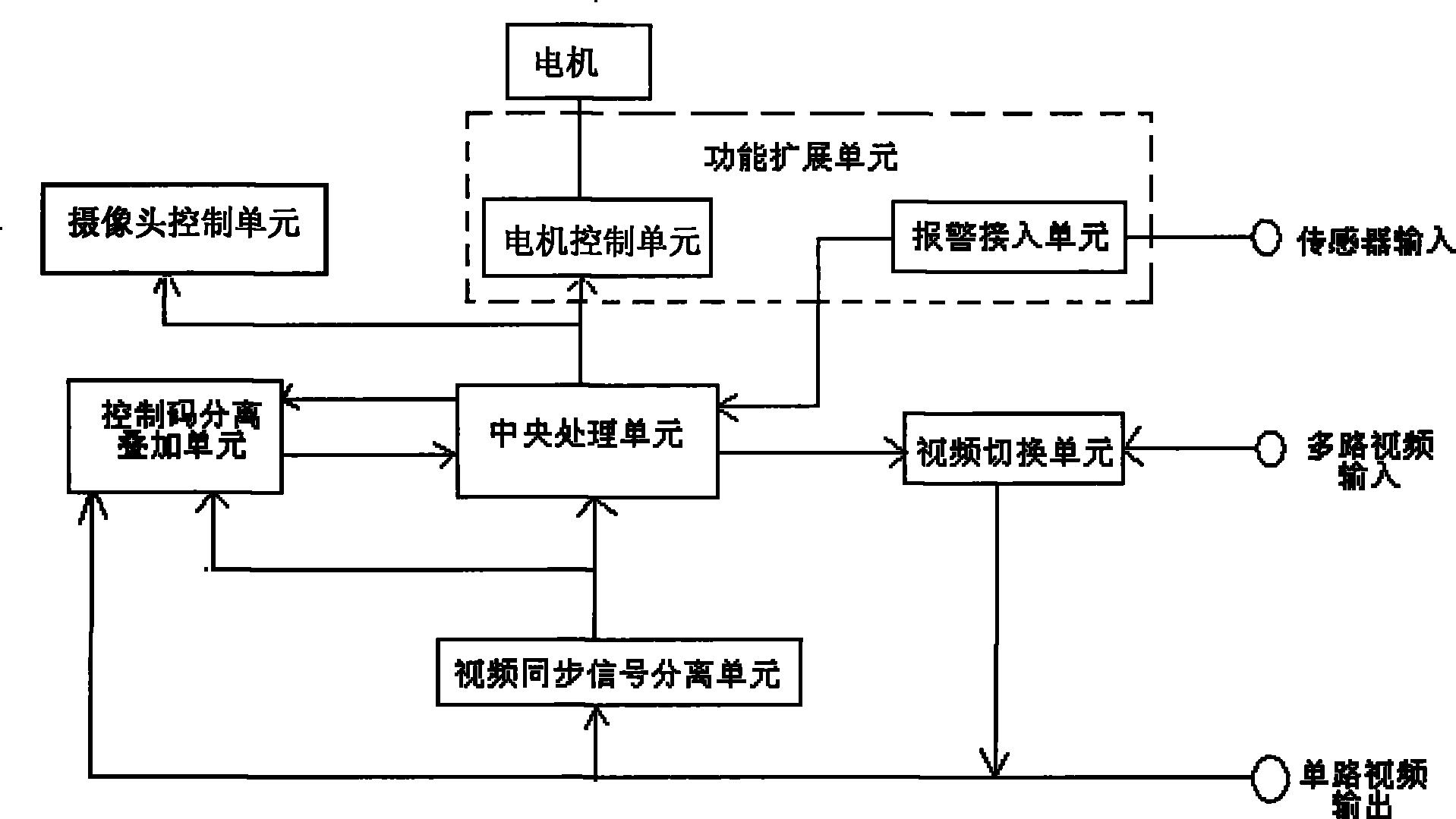
[0037] In the second embodiment, the principle diagram of the extended f...


PUM


Abstract

The invention discloses a rotational-free panoramic photography device and a monitoring system comprising same, comprising a video electronic switching control plate and cameras. The video electronic switching control plate comprises a central processing unit, a control code separation and overlapping unit, a video switching unit and a video synchronization signal separation unit; and the rotational-free panoramic photography device adopts N cameras, shoots N intervals formed by dividing a monitored 360-degree panoramic space, the N is greater than or equal to 2, and the monitoring system adopting the rotational-free panoramic photography device transmits a control code and N paths of video images on the same video transmission line by a time-sharing transmission technique. The invention needs no motor to mechanically control the cameras, prolongs the service life of the photography device, reduces the power consumption and the wiring cost of the photography device and does not lose the quality of the video images. The invention can realize the integration of theft prevention and video monitoring by adding a motor control unit and a warning access unit.

Description

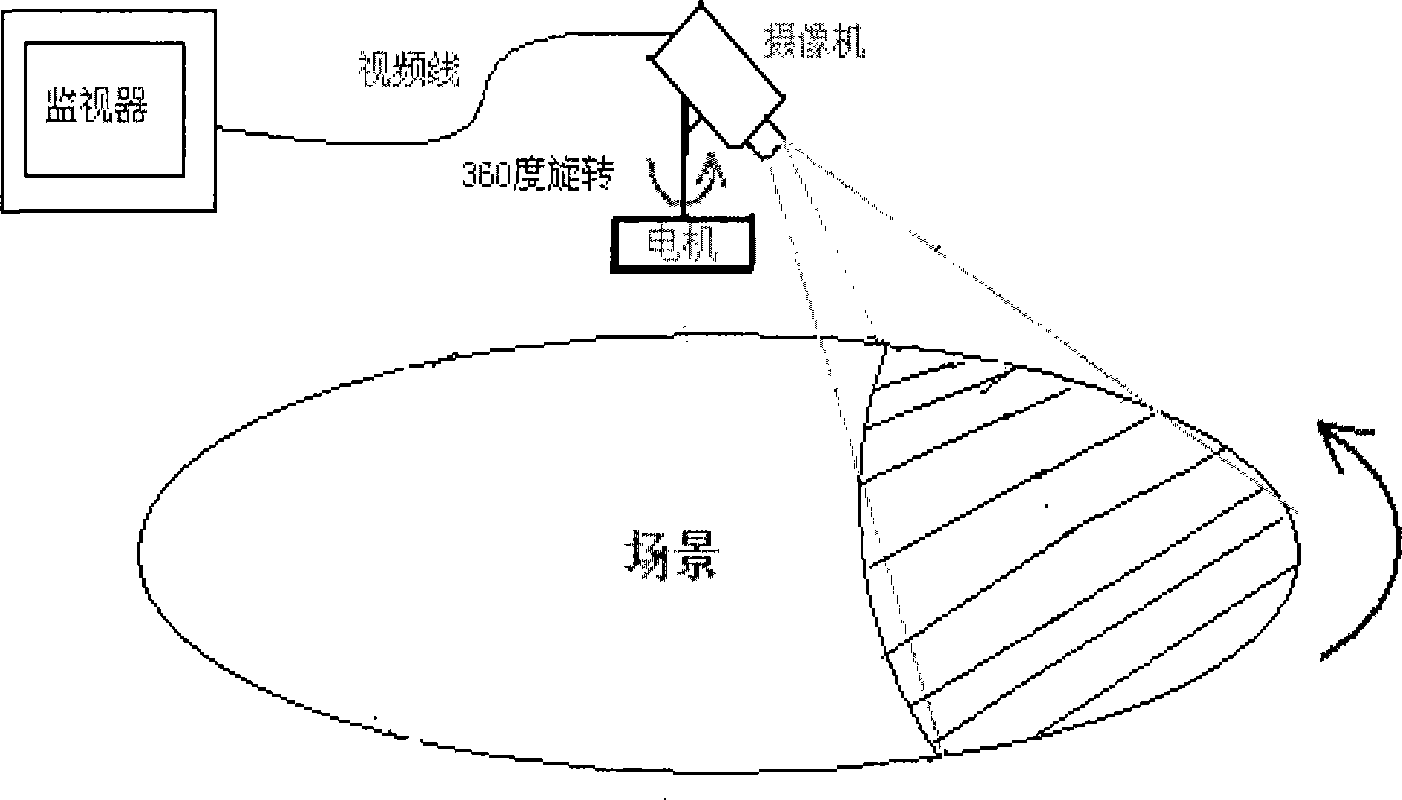
technical field [0001] The invention relates to a camera device for video monitoring, in particular to a non-rotating panoramic camera device and a monitoring system formed therefrom. Background technique [0002] In the field of electronic security, a camera is usually used to shoot a certain scene in real time to complete the video surveillance within the range. If you want to realize the panoramic monitoring in the 360-degree space of the scene, you need to drag the camera through the motor to do a 360-degree horizontal scanning movement, such as figure 1 shown. During the rotation of the motor, there is mechanical friction in the rotation of the bearing or the sliding brush, and the motor that runs continuously for a long time will inevitably wear out quickly. At the same time, adjusting the speed of the motor involves the speed regulation control of the motor. The speed regulation control process of the motor is relatively complicated, and the control accuracy and sen...

Claims


Application Information

Patent Timeline
Patent Type & Authority Patents(China)
IPC IPC(8): H04N7/18H04N5/268G08B13/196
Inventor 龙细军
Owner ZTE CORP
Learn More