
Processing method for chute in casing of hydraulic pump

A technology of hydraulic pump casing and processing method, which is applied in the field of hydraulic pumps and can solve the problems of expensive manufacturing of hydraulic pump casings and the like

Inactive Publication Date: 2009-11-04
SHANGHAI ELECTRICAL HYDRAULICS & PNEUMATICS
View PDF0 Cites 2 Cited by
  • Summary
  • Abstract
  • Description
  • Claims
  • Application Information

AI Technical Summary

Problems solved by technology

Therefore, existing hydraulic pump housings are very expensive to manufacture

Method used


Image

  • Processing method for chute in casing of hydraulic pump

Examples


Embodiment Construction

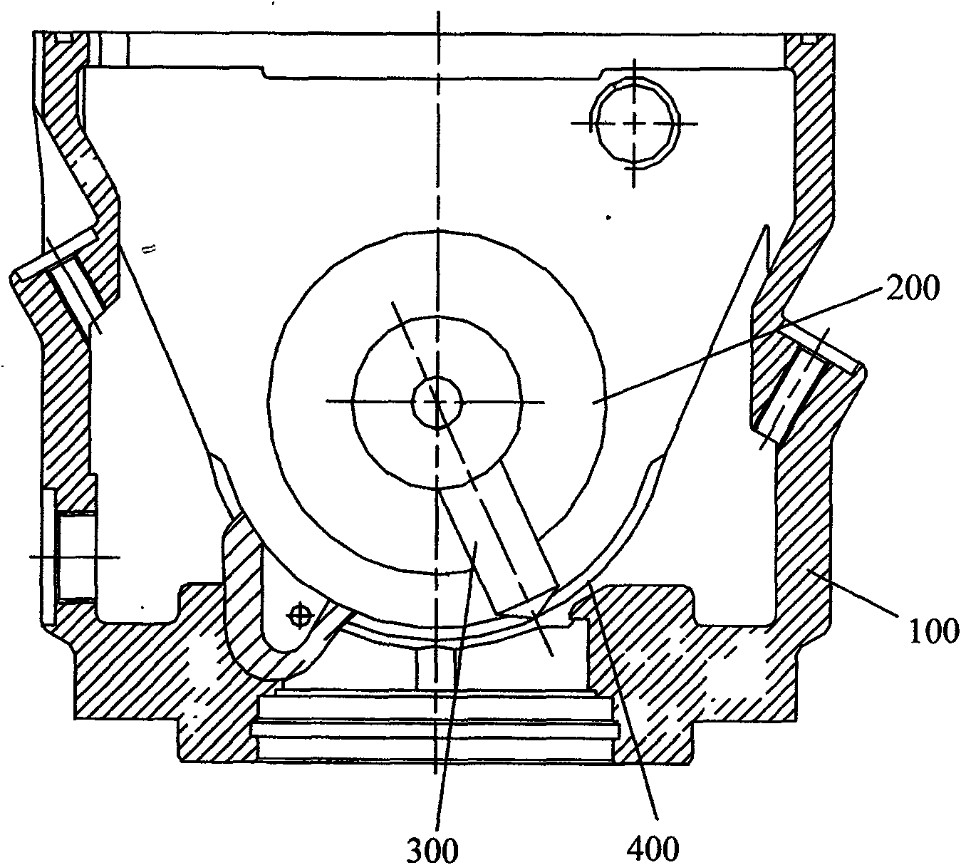
[0013] Such as figure 1 As shown, the processing method of the chute in the housing of the hydraulic pump of the present invention is to open a window 200 on both sides of the housing 100, and then insert the machining tool head 300 of an ordinary numerical control machine tool into the housing 100 from the window 200 on one side. Inside, the chute 400 is processed on the opposite side wall until the chute 400 is processed to meet the size requirements and precision requirements.

[0014] In the present invention, the two opened windows 200 are circular symmetrical windows, and the size of the windows 200 is such that the machining tool head 300 can penetrate into the housing 100 without affecting the strength of the housing 100 .

[0015] Ordinary CNC machine tools are ordinary horizontal CNC machining centers.

[0016] By opening the window 200 on the side of the housing 100, the processing cutter head of the ordinary CNC machine tool can be inserted into the inside of the ...


PUM


Abstract

The invention relates to a processing method for chutes in the casing of a hydraulic pump. According to the method, windows are opened on the both sides of the casing respectively; and then a processing tool bit of a common numerical control machine tool extends into the casing via the windows to process two chutes. The chutes in the casing of the hydraulic pump have the advantage of processing high precision chutes through the common numerical control machine tool. The method has a simple process and low processing cost.

Description

technical field [0001] The invention belongs to the technical field of hydraulic pumps, and relates to a casing of a hydraulic pump, in particular to a processing method for a chute in the casing of a hydraulic pump. Background technique [0002] There are two slide grooves in the housing of the hydraulic pump. The transmission mechanism of the hydraulic pump is installed on the housing through these two slide grooves and planing bearings. On the one hand, the position of the chute is at the bottom of the housing. On the other hand, the chute is partly in the shape of an inner cylinder, which requires extremely high machining accuracy and surface roughness. These make it very difficult to process a high-precision chute. difficulty. At present, the processing of this kind of chute at home and abroad mainly adopts high-precision machining equipment, such as a five-axis linkage CNC machining center, but the price of a machining center is generally more than 8 million. Theref...

Claims


Application Information

Patent Timeline
Patent Type & Authority Applications(China)
IPC IPC(8): B23B1/00
Inventor 李斌陈俊龙
Owner SHANGHAI ELECTRICAL HYDRAULICS & PNEUMATICS
Learn More