
Plate spring type welding clamp

A technology of electric welding tongs and leaf springs, which is applied to the characteristics of welding rods, electrode support devices, etc., can solve problems such as hot handles, and achieve a reasonable design effect

Inactive Publication Date: 2009-11-04
范垂
View PDF2 Cites 1 Cited by
  • Summary
  • Abstract
  • Description
  • Claims
  • Application Information

AI Technical Summary

Problems solved by technology

[0004] The object of the present invention is to provide a leaf spring electric welding tongs with a unique structure that uses leaf springs to replace traditional steel wire cylindrical compression springs, which fundamentally solves the problem of hot handles caused by continuous welding of existing electric welding tongs. The advantages of reasonable structure and appearance design can significantly save conductor materials, reduce manufacturing costs, prolong service life, and truly make continuous welding without hot hands, improving work efficiency

Method used


Image

  • Plate spring type welding clamp
  • Plate spring type welding clamp
  • Plate spring type welding clamp

Examples


Embodiment Construction

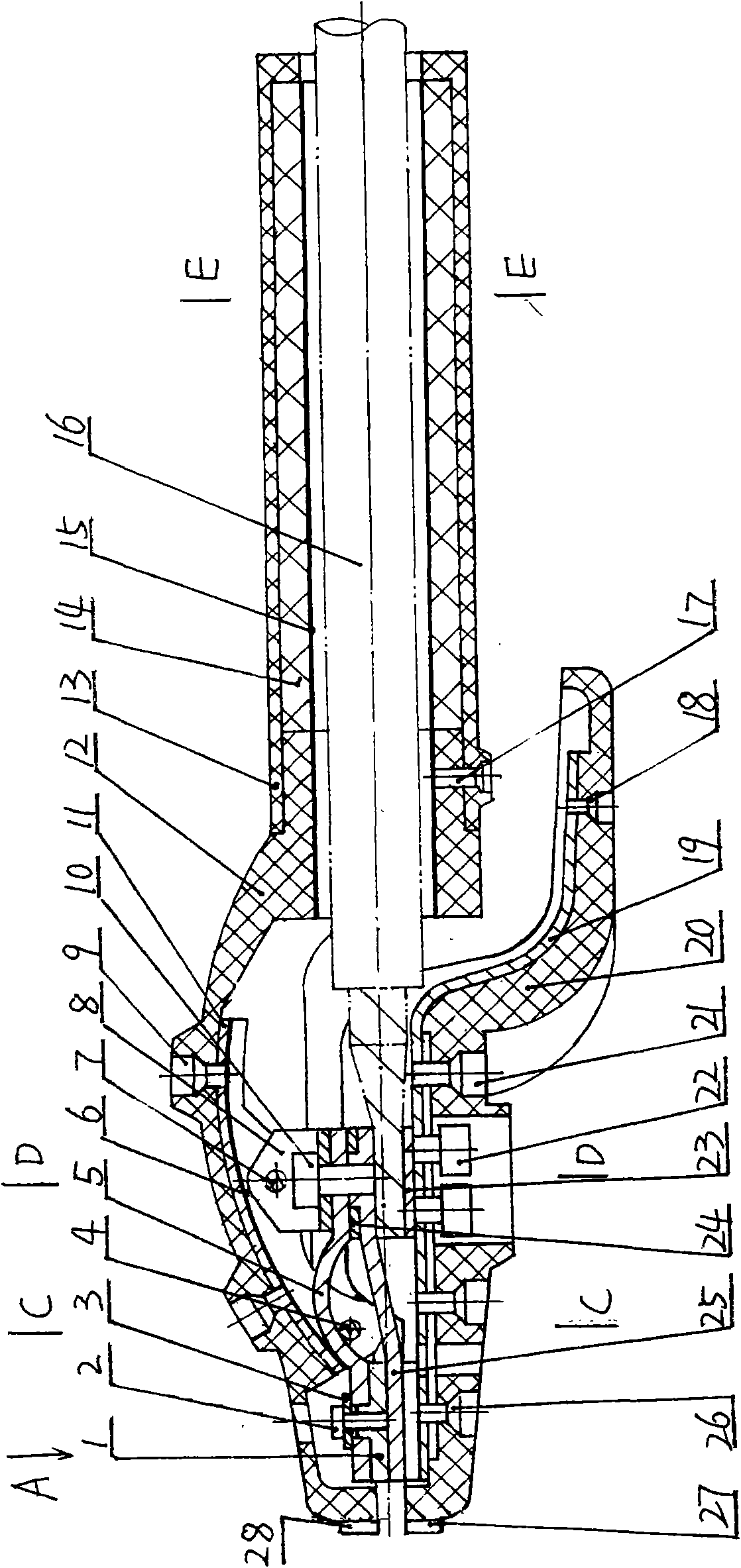
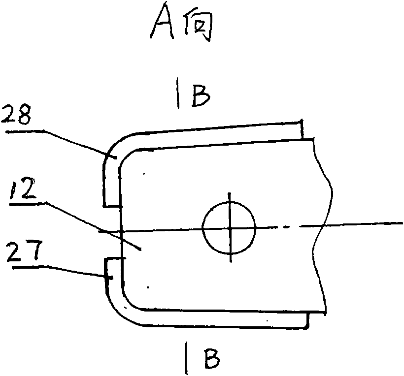
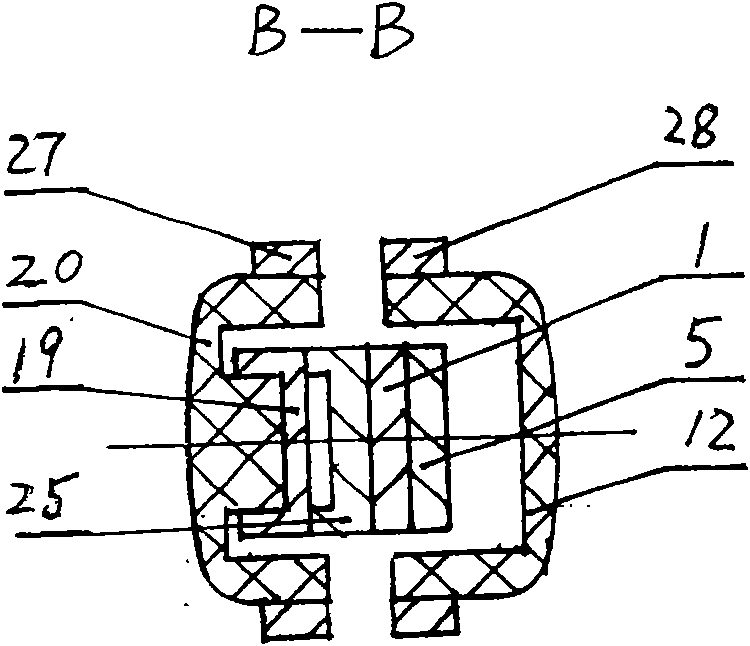
[0023] according to Figure 1-9 To describe the specific structure of the present invention in detail, the leaf spring electric welding tongs includes a handle assembly and a lower insulator assembly. The handle assembly includes handle insulator 13, heat insulation tube 14, aluminum foil heat-resistant reflective cylinder 15, upper insulator 12, coupling shaft 7, lifting spring shaft 4, lifting spring frame 11, aluminum foil heat-resistant reflective layer 6, screws 9, 17 , Upper temperature-resistant protective layer 28 and the like. The lower insulator assembly includes upper jaw 1, plate spring 5, support frame 8, cable 16, pressure plate 23, lower insulator 20, washer 3, screws 2, 26, 22, 21, 18, skeleton plate 19, connection frame 24 , the lower jaw 25, the lower temperature-resistant protective layer 27 and the like.

[0024] The inwall of the upper insulator 12 of the handle assembly utilizes screws 9 to fix the lifting spring frame 11 that the lifting spring shaft 4...


PUM


Abstract

The invention relates to a plate spring type welding clamp using a plate spring to replace the prior steel wire cylindrical compression spring. Because of a unique structure, the plate spring type welding clamp fundamentally solves the problem that a handle of the prior welding clamp scalds hands in continuous welding. The plate spring type welding clamp comprises a handle assembly and a lower insulator assembly, and the technical key points comprise that a lower insulator in the lower insulator assembly is provided with the plate spring, and the plate spring is fixedly connected with a connecting frame and a supporting frame of the lower insulator. The inner wall of an upper insulator of the handle assembly is provided with a spring-uplifting frame provided with a spring-uplifting shaft and a connection shaft, the supporting frame is hinged with the connection shaft, and the other end of the plate spring is interconnected with the spring-uplifting shaft of the spring-uplifting frame of the upper insulator. The original structure of the plate spring type welding clamp not only has reasonable design, and can shorten a conductor of a lower clamp jaw and save the conductor remarkably, but also can reduce the production cost, remarkably prolong the service life, really achieve the continuous welding without scalding the hands, and improve the working efficiency.

Description

technical field [0001] The invention relates to an arc welding device for continuous welding of AC and DC, in particular to a plate spring which replaces the steel wire cylindrical compression spring of the traditional structure to obtain the clamping force of the welding rod and the handle is not hot during continuous welding. Welding clamp. Background technique [0002] At present, the clamping force of the electric welding pliers at home and abroad mostly comes from the steel wire cylindrical compression spring of the traditional structure, that is, the upper jaw of the electric welding pliers joystick assembly and the lower insulator connected with the handle insulator of the handle assembly. The lower pliers mouth connected by the cable is used to clamp the electrode by the compression of the compression spring. After a period of use, the clamping force of the electrode will be significantly weakened with the elastic fatigue of the steel wire cylindrical compression spr...

Claims


Application Information

Patent Timeline
Patent Type & Authority Applications(China)
IPC IPC(8): B23K9/28
Inventor 范垂顺
Owner 范垂
Learn More