Method for lapping orifice silicon core capable of effectively improving contact area and reducing resistance

A contact area and silicon core technology, which is applied in chemical instruments and methods, silicon compounds, crystal growth, etc., can solve the problems of inability to locate in the left and right directions, poor quality of polysilicon, and high resistance at overlapping joints, so as to avoid lodging of silicon cores, The effect of improving quality and improving firmness

Active Publication Date: 2009-11-04
LUOYANG JINNUO MECHANICAL ENG
View PDF0 Cites 23 Cited by
  • Summary
  • Abstract
  • Description
  • Claims
  • Application Information

AI Technical Summary

Problems solved by technology

[0004] First, the contact surface at the lap joint is too small, resulting in poor contact at the lap joint and a correspondingly large resistance. During the reduction reaction, the quality of the polysilicon obtained here is poor, which is called "bending material" in jargon;
[0005] Second, it can be positioned by U-shaped or V-shaped grooves in the front-to-back direction, but it cannot be positioned in the left-right direction. In this way, it is easy to cause the silicon core to fall during the reduction process.

Method used


Image

  • Method for lapping orifice silicon core capable of effectively improving contact area and reducing resistance
  • Method for lapping orifice silicon core capable of effectively improving contact area and reducing resistance
  • Method for lapping orifice silicon core capable of effectively improving contact area and reducing resistance

Examples


Embodiment Construction

[0034] The utility model can be explained in more detail with reference to the following examples, but the utility model is not limited to these examples.

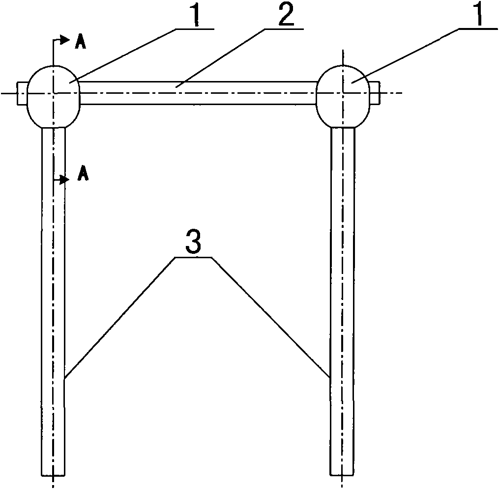
[0035] exist Figure 4 , 5 Middle; A hole-type silicon core overlapping method that can effectively improve the contact area and reduce the resistance, the concrete steps of the present invention are;

[0036] 1), first draw the horizontal silicon core 2 with silicon core spheres 1 at both ends of the required length;

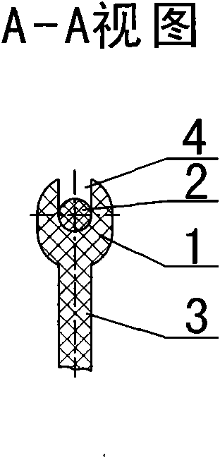
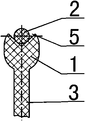
[0037] 2), drill a socket or a slot 6 on the silicon core sphere 1 at both ends of the horizontal silicon core 2;

[0038] 3), grinding the upper end of the vertical silicon core 3 into a shape that matches the hole or slot 6 drilled on the silicon core sphere 1;

[0039] 4), insert the upper end of the vertical silicon core 3 into the jack or slot 6 on the silicon core sphere 1 at both ends of the horizontal silicon core 2, and confirm whether it is firm. The jacks or slots 6 on the silicon core sphere...


PUM


Abstract

The invention provides a method for lapping an orifice silicon core capable of effectively improving the contact area and reducing resistance, and belongs to a method for lapping the silicon core in a process for producing polysilicon by Siemens method. The method comprises the following steps: a horizontal silicon core (2) with required length and silicon core spheres (1) on two ends is drawn; jacks or slots (6) are drilled on the silicon core spheres (1) on two ends of the horizontal silicon core (2); and shapes matched with the jacks or the slots (6) drilled on the silicon core sphere (1) are polished on the upper end of a vertical silicon core (3) jacks or slots (6) on silicon core spheres (1) which is on the two ends of horizontal silicon core (2) is inserted on the upper end of the vertical silicon core. The method ensures that the lapped silicon cores have larger contact surface on the lapping position, so that the silicon core has better conductive performance, thereby improving the quality of the polysilicon in polysilicon production. Furthermore, the firmness of the silicon core can be greatly improved by adopting orifice lapping technology, and silicon core lodging in the production process can be avoided.

Description

Technical field: [0001] The invention belongs to a silicon core overlapping method in the process of producing polysilicon by Siemens method, in particular to a hole type silicon core overlapping method which can effectively increase the contact area and reduce resistance. Background technique: [0002] At present, silicon core bonding technology is a very important technology in the process of polysilicon production by Siemens method. It is mainly used in a link of polysilicon production, that is, the reduction reaction process. The principle of the reduction reaction process is: the reduction reaction is carried out in a closed reduction furnace, and several closed loops are formed by lapping silicon cores in the reduction furnace before loading the furnace, which is the "bridge" in the jargon. "; each closed circuit is made up of two vertical silicon cores (3) and a horizontal silicon core (2); figure 1 , 2 Or in the prior art shown in 3, two vertical silicon cores (3) ...

Claims


Application Information

Patent Timeline
Patent Type & Authority Applications(China)
IPC IPC(8): C30B29/06C30B28/14C01B33/035
Inventor 刘朝轩
Owner LUOYANG JINNUO MECHANICAL ENG
Why Eureka
Try Eureka