
Data writing method, quick flashing memory system using same and a controller thereof

A data writing and storage system technology, applied in the direction of memory address/allocation/relocation, etc., can solve problems such as inability to use flash memory, and achieve the effect of preventing timeout problems and shortening time

Active Publication Date: 2009-11-04
PHISON ELECTRONICS
View PDF0 Cites 23 Cited by
  • Summary
  • Abstract
  • Description
  • Claims
  • Application Information

AI Technical Summary

Problems solved by technology

Due to the progress of the flash memory process and in order to meet the trend of large-capacity storage media, the design capacity of each programming unit and erasing unit will become larger and larger, and this will require more time to move the memory in the erasing unit. valid data
However, such large-capacity erasable flash memory units often have a response time of data writing commands that exceed some of the latest flash memory systems (such as solid state drives (Solid State Drive, SSD)), so it is impossible to use this kind of flash memory with a large capacity erasing unit

Method used


Image

  • Data writing method, quick flashing memory system using same and a controller thereof
  • Data writing method, quick flashing memory system using same and a controller thereof
  • Data writing method, quick flashing memory system using same and a controller thereof

Examples


no. 1 example

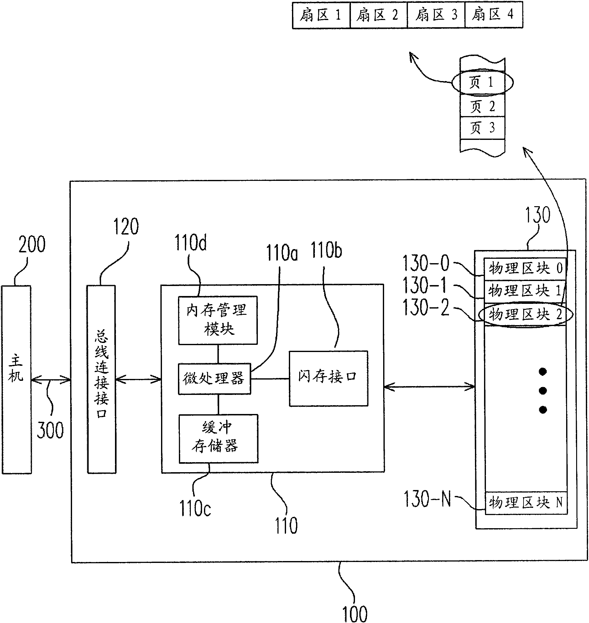
[0059] figure 1 is a schematic block diagram illustrating a flash memory system according to a first embodiment of the present invention. Please refer to figure 1 , the flash storage system 100 includes a controller 110 , a bus connection interface 120 and a flash memory 130 . Generally, the flash storage system 100 is used together with the host 200 so that the host 200 can write data into the flash storage system 100 or read data from the flash storage system 100 . In this embodiment, the flash memory system 100 is a solid state drive (SSD). But it must be understood that in another embodiment of the present invention, the flash memory system 100 may also be a memory card or a flash drive.

[0060] The controller 110 coordinates the overall operation of the bus connection interface 120 and the flash memory 130 , such as writing, reading and erasing of data. The controller 110 includes a microprocessor 110a, a flash memory interface 110b, a buffer memory 110c and a memory...

no. 2 example

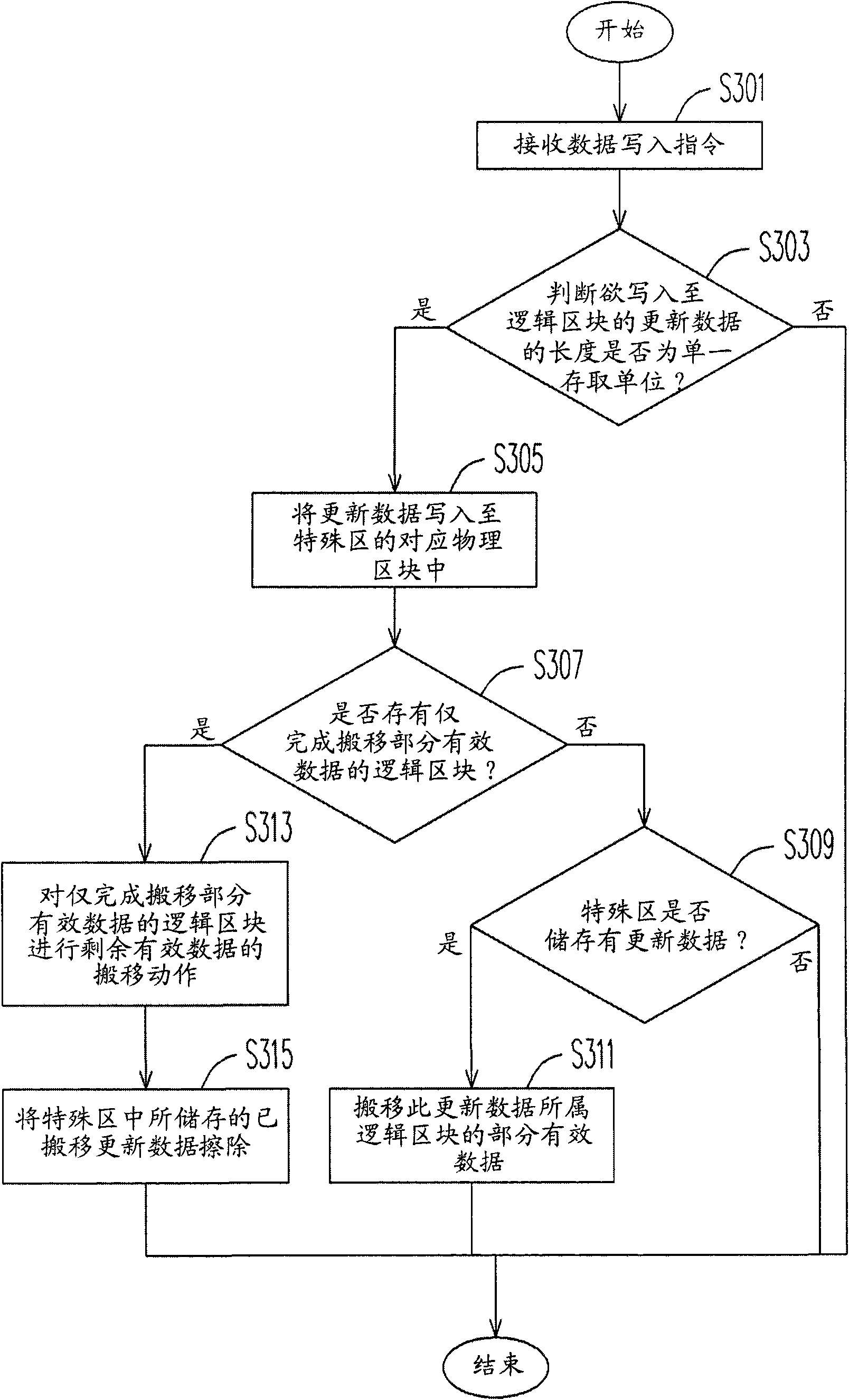
[0092] In the first embodiment of the present invention, when the update data is stored in the physical block of the special area, the effective data transfer operation of the logical block to which the update data belongs is immediately started. However, the present invention can also be applied to move the effective data of the same logical block when there are multiple pieces of update data belonging to the same logical block in the physical block of the special area. In this embodiment, two pieces of update data belonging to the same logical block are stored in the physical block of the special area as an example for illustration.

[0093] The hardware architecture of the second embodiment of the present invention is the same as that of the first embodiment (such as figure 1 and figure 2 shown), and will not be repeated here. The difference between the second embodiment and the first embodiment is that the data writing step performed in the second embodiment is performe...


PUM


Abstract

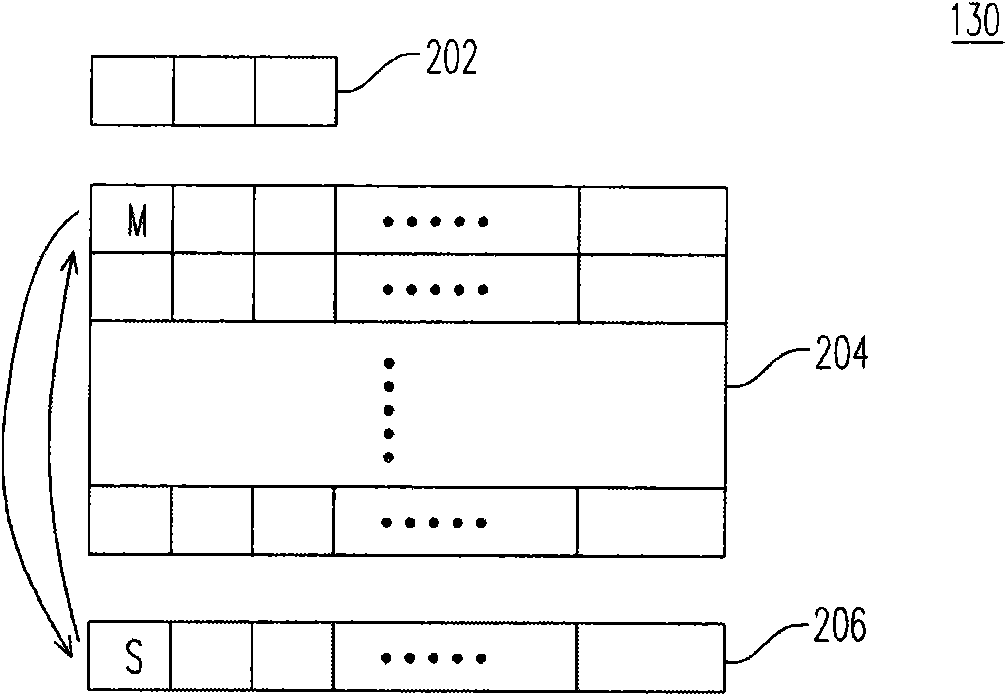
The invention provides a data writing method, a quick flashing memory system using the same and a controller thereof. The data writing method comprises the following steps: logically grouping a physical block of a flash memory into a data area, a spare area and a special area; then judging whether the refresh data to be written in a logical block by a host is a single access unit or not accordingto data writing commands received from the host, wherein if the refresh data is the single access unit, writing the refresh data in the corresponding physical block of the special area; and transferring the effective data in the physical block corresponding to the logical block in a graded mode in the process of writing commands for a plurality of data, in this way, the response time for data writing commands can be shortened to prevent the probability of overtime generated in a memory system using a flash memory with high-capacity erasing units.

Description

technical field [0001] The invention relates to a data writing method, and in particular to a data writing method for flash memory, a flash storage system using the method and a controller thereof. Background technique [0002] Digital cameras, cell phone cameras, and MP3 players have grown rapidly in recent years, making consumers' demand for storage media also increase rapidly. Because flash memory (Flash Memory) has the characteristics of data non-volatility, power saving, small size and no mechanical structure, it is suitable for portable applications, and is most suitable for such portable products powered by batteries. A memory card is a storage device that uses a NAND flash memory as a storage medium. Due to its small size, large capacity and easy portability, memory cards have been widely used for storing important personal data. Therefore, the flash memory industry has become a very popular part of the electronics industry in recent years. [0003] Generally spea...

Claims


Application Information

Patent Timeline
Patent Type & Authority Applications(China)
IPC IPC(8): G06F12/02G06F12/06
Inventor 杨俊勇叶志刚
Owner PHISON ELECTRONICS
Learn More