Heat dissipation system of underground box type transformer

A technology of box-type transformer and heat dissipation system, which is applied in the direction of transformer/inductor cooling, substation/switchgear cooling/ventilation, etc., which can solve the difficulty of adapting to the trend of miniaturization of transformer pit boxes and meet the heat dissipation requirements of transformers , the small external space of the transformer, etc., to achieve effective heat dissipation, safe and durable use, and high heat dissipation effect

Active Publication Date: 2011-07-27
基元电气有限公司
View PDF0 Cites 0 Cited by
  • Summary
  • Abstract
  • Description
  • Claims
  • Application Information

AI Technical Summary

Problems solved by technology

[0004] (1) It is difficult to adapt to the trend of miniaturization of the transformer pit box
Due to the complex intertwining of modern urban underground pipe networks and the tendency to become more and more crowded, the space available for placing pre-installed transformers in the urban underground is increasingly limited, resulting in more and more requirements for the floor area of ​​the transformer pit box. With the trend of getting smaller and smaller, the external space of the transformer located in the pit box is getting smaller and smaller, making it difficult for the existing heat dissipation system that mainly relies on air convection to dissipate heat to meet the heat dissipation requirements of the transformer for long-term safe operation, and it has become the popularization and use of underground box-type transformers. the bottleneck
[0005] (2) Once the forced ventilation mechanism fails, if it is not found and repaired in time, it is still easy to cause the transformer to fail due to overheating

Method used


Image

  • Heat dissipation system of underground box type transformer
  • Heat dissipation system of underground box type transformer
  • Heat dissipation system of underground box type transformer

Examples


Embodiment 1

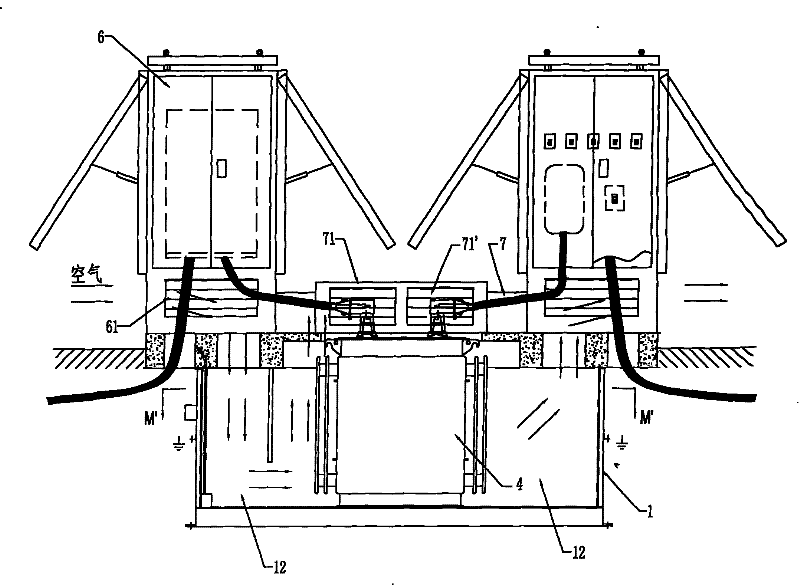
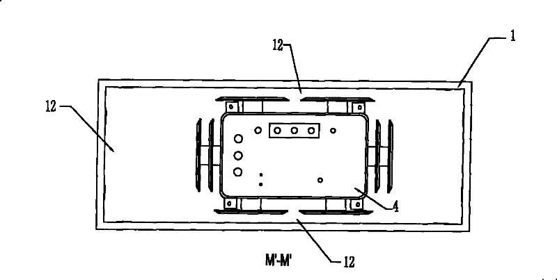
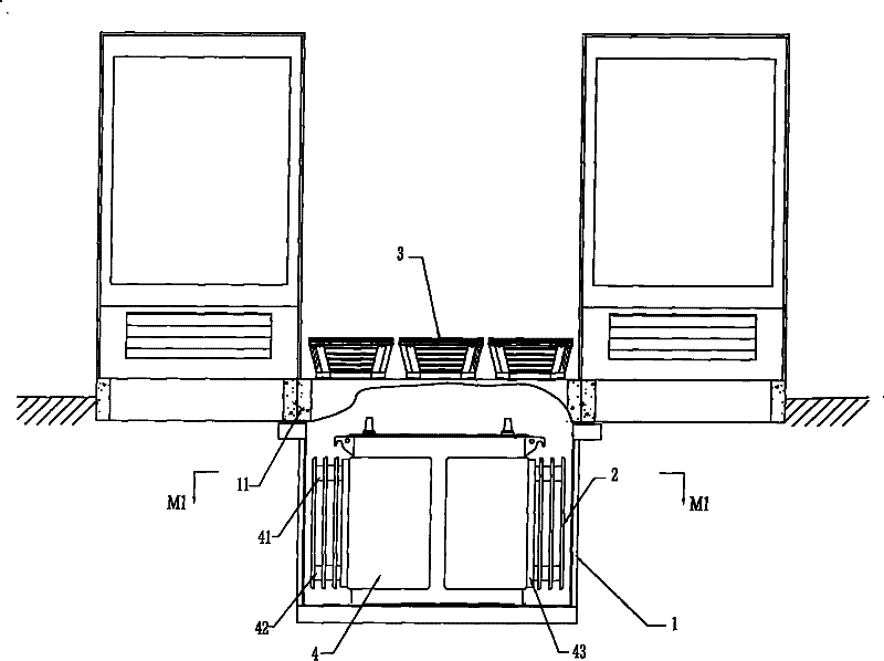
[0039] Figure 3 ~ Figure 4 The heat dissipation system of an underground box-type transformer shown is Embodiment 1 of the present invention, which includes a natural convection heat dissipation mechanism and an enhanced heat exchange mechanism, wherein the structure of the natural convection heat dissipation mechanism is: the oil-immersed transformer body 4 is arranged on There is a cavity 12 in the prefabricated pit box 1 and between the inner wall of the pit box 1. The cavity 12 is used as a ventilation channel and a vent on the ground to form a natural convection heat dissipation system. The vent includes The ventilation hood 3 provided on the pit cover 11 and the ventilation opening 61 through which the power distribution cabinet 6 communicates with the outside world (ie air). The enhanced heat exchange mechanism is composed of a heat sink and a connecting piece connecting the heat sink to the outer wall of the oil-immersed transformer body 4. In this embodiment, two rei...

Embodiment 2

[0043] Figure 5 ~ Figure 8 The radiating system of a kind of underground box-type transformer shown is the embodiment 2 of the present invention, and it is different from embodiment 1 in that: each enhanced heat exchange mechanism outermost radiator and pit box 1 inner wall leave There is a gap; and between the four enhanced heat exchange mechanisms installed in the two long directions of the transformer body 4 and the inner wall of the pit box 1, there are metal heat transfer parts. The metal heat transfer parts are composed of a pair of elastic parts with good thermal conductivity. It consists of a hollow triangular wedge 51 with right-angled sides made of material. The hypotenuses of a pair of right-angled wedges 51 are opposite and in contact, and the parallel right-angled sides are respectively in contact with the heat sink 2 and the inner wall of the pit box 1 and are clamped between the outermost heat sink and the inner wall of the pit box 1, so as to Conduct the heat...

Embodiment 3

[0046] Figure 9 ~ Figure 11 The heat dissipation system of a kind of underground box-type transformer shown is embodiment 3 of the present invention, and it is different from embodiment 1 in that: the enhanced heat exchange mechanism installed in the two short directions of transformer body 4 is equipped with oil inlet pipe and oil outlet pipe Two heat sinks, and there is a gap between the outermost heat sink and the inner wall of the pit box 1; the enhanced heat exchange mechanism installed in the two long directions of the transformer body 4 is provided with a heat dissipation plate that is in contact with the inner wall of the pit box sheet, and the connector used for connection is an elastic corrugated heat transfer tube 52, the corrugated heat transfer tube is arranged between the transformer body and the heat sink, and its two ends are connected with the transformer and the heat sink respectively, and the corrugated heat transfer tube is connected to the pit The inner w...


PUM


Abstract

The invention discloses a heat dissipation system of an underground box type transformer, comprising a natural convection heat dissipation system mechanism formed by air chutes arranged around a transformer body in a pit box and a ventilation opening arranged on the ground. The heat dissipation system is characterized by further comprising a reinforced heat exchange mechanism which is arranged onat least one outer wall of the transformer body (4) and contacted with the inner wall of the pit box (1), so that the heat generated by the transformer body (4) is transmitted into the pit box (1) through the reinforced heat exchange mechanism, and the heat is then transferred into the surrounding stratum through the pit box. The heat dissipation system combines natural ventilation and forced ventilation, and adopts surface soil layer heat dissipation, so as to improve the heat dissipation effect and ensure lasting and stable heat dissipation; furthermore, the size of the pit box can be reduced to the utmost extent, and the pre-buried underground space is saved.

Description

technical field [0001] The invention relates to a heat dissipation system of an underground box-type transformer, in particular to a heat dissipation system which utilizes surface soil layers to dissipate heat to improve the heat dissipation effect and ensure long-lasting and stable heat dissipation. Background technique [0002] The pre-installed underground box-type transformer is one of the most commonly used transformers at present. Its transformer is buried in the pit box. This structure can greatly save the space above the ground. But this type of transformer body is completely buried below the ground surface, so the heat generated when it works is easily confined in the narrow space between it and the pit box, see figure 1 , 2 , the existing pre-installed underground box-type transformer includes a transformer body 4, a power distribution cabinet 6, and a prefabricated pit box 1. The cabinet 6 is connected, and some designs also include a pit operation box 7 on the ...

Claims


Application Information

Patent Timeline
Patent Type & Authority Patents(China)
IPC IPC(8): H01F27/08H02B1/56
Inventor 冯骏明
Owner 基元电气有限公司
Why Eureka
Try Eureka