
Optical fiber grating anchor stress sensor

An anchor stress and fiber grating technology is applied in the direction of force measurement by measuring the change of optical properties of materials when they are stressed, and can solve problems such as unfavorable use, difficult control, and non-adjustable sensor detection coefficients.

Inactive Publication Date: 2009-11-11
LASER RES INST OF SHANDONG ACAD OF SCI +1
View PDF0 Cites 14 Cited by
  • Summary
  • Abstract
  • Description
  • Claims
  • Application Information

AI Technical Summary

Problems solved by technology

The detection coefficient of the sensor cannot be adjusted
Moreover, the pasting of the grating needs to be pre-stretched to a large extent, so it is not easy to control, and the axial height of the sensor is too large to be unfavorable for use.

Method used


Image

  • Optical fiber grating anchor stress sensor
  • Optical fiber grating anchor stress sensor
  • Optical fiber grating anchor stress sensor

Examples


Embodiment Construction

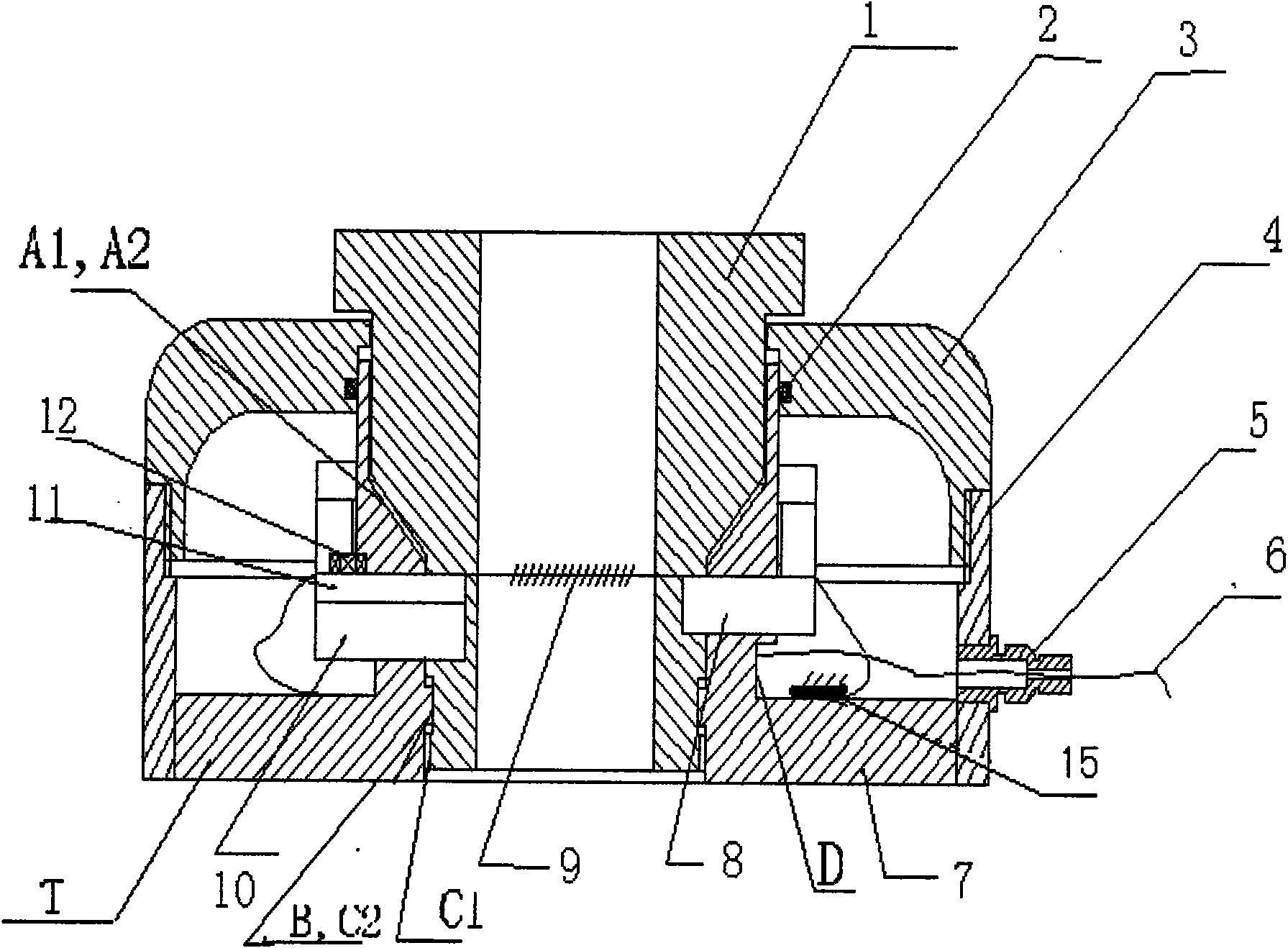
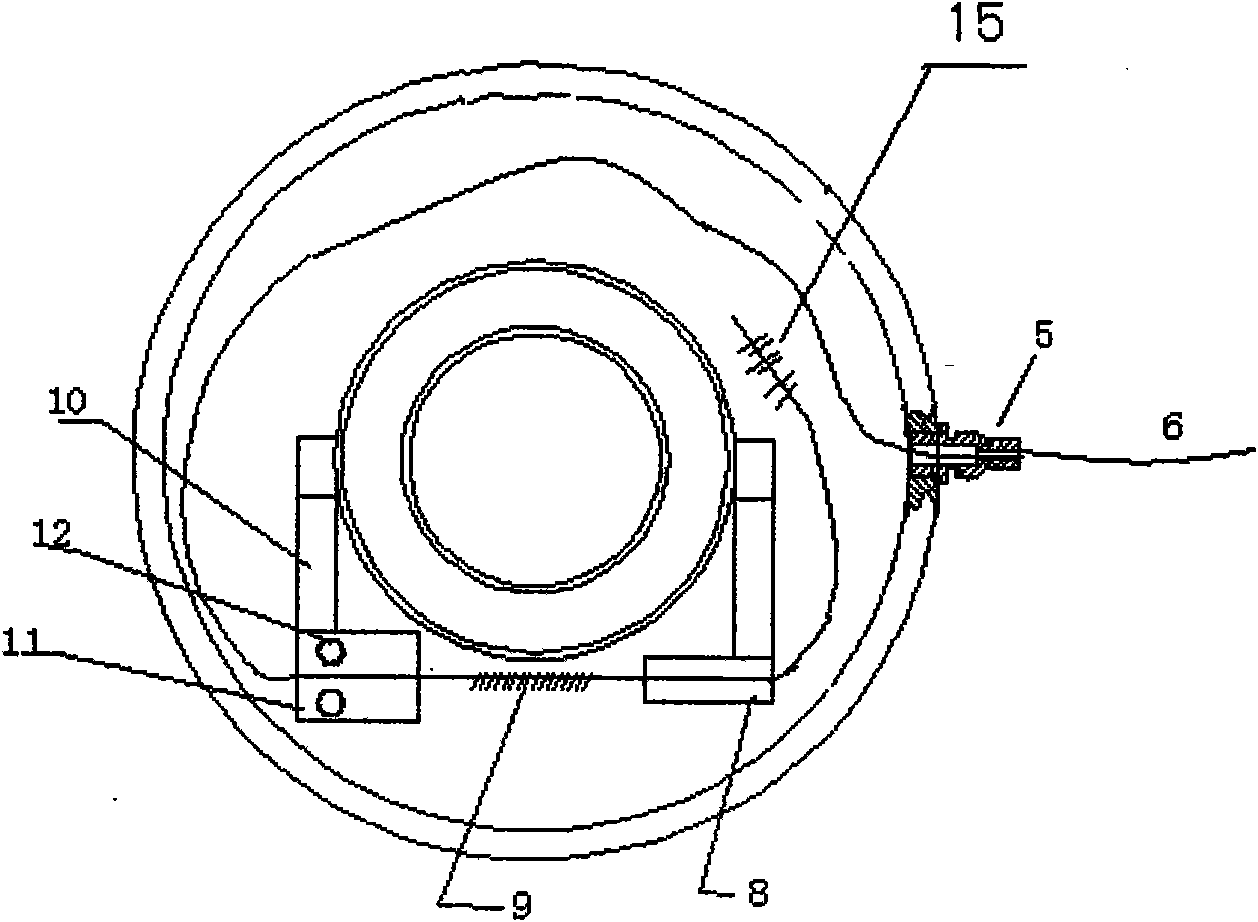
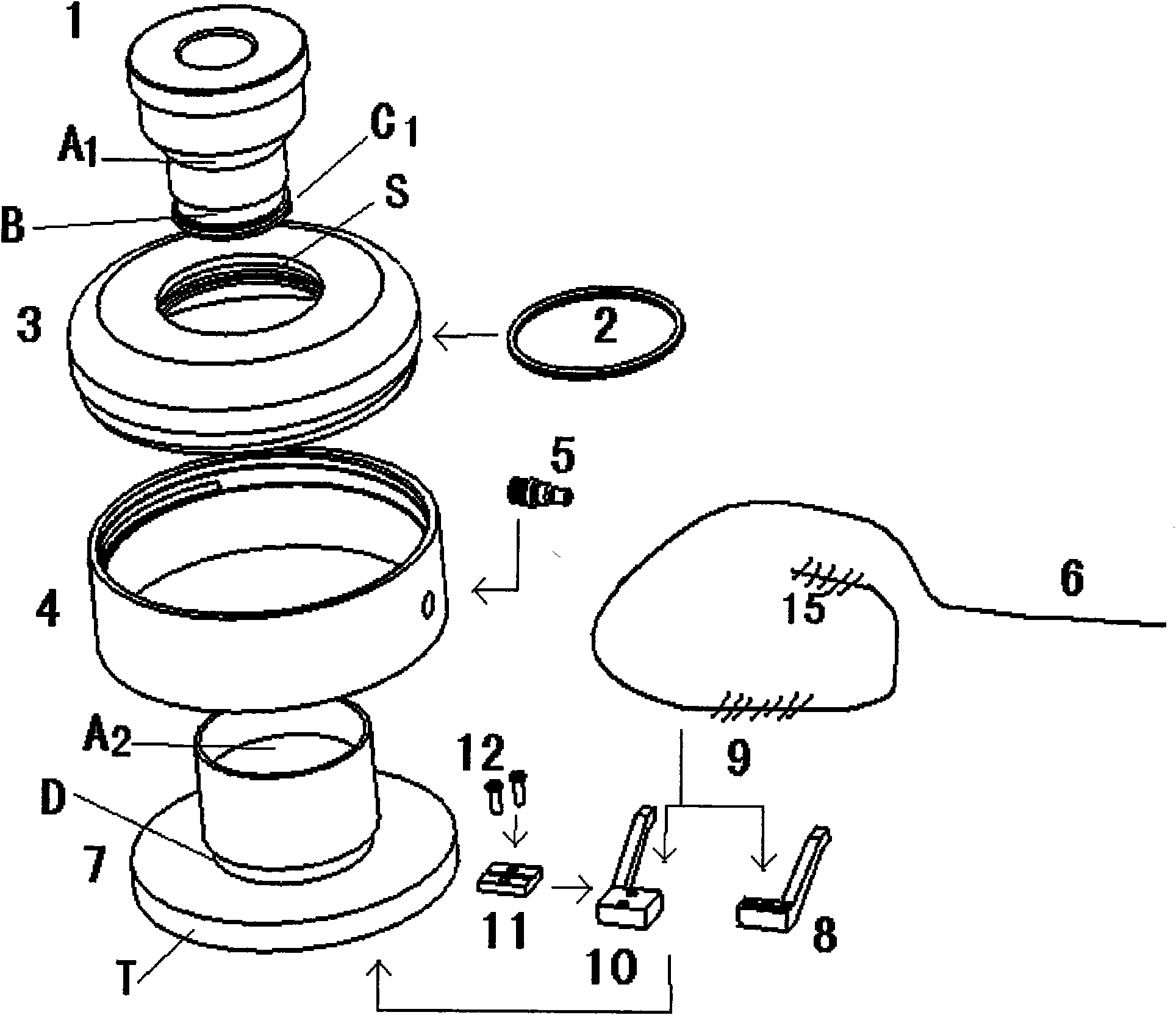
[0024] Such as Figure 1-2 As shown, it includes a force-measuring base 7 and a first fiber Bragg grating 9 arranged on the force-measuring base 7. The first fiber Bragg grating 9 is connected to an optical wavelength demodulator through an optical fiber 6. The force-measuring base 7 It is a hollow structure and includes a head, a neck and a shoulder T. The force-measuring base 7 has a built-in force-transmission nut 1. The upper and lower parts of the force-transmission nut 1 are cylinders, and the middle part is a circular platform. The force-transmission nut 1 1 is compatible with the inner cavity of the force-measuring base 7, and the force-transmitting slope A1 on the outer edge of the round platform on the force-transmitting nut 1 is the contact surface with the force-bearing slope A2 on the inner wall of the force-measuring base 7; on the outer wall of the force-measuring base 7 A fixed bracket 8 and an adjustable bracket 10 are provided corresponding to the position of...


PUM


Abstract

The invention relates to an optical fiber grating anchor stress sensor, which comprises a force measuring pedestal and a first prague optical fiber grating which is arranged on the force measuring pedestal, wherein the first prague optical fiber grating is connected with an optical wavelength demodulator through optical fiber; the force measuring pedestal has a hollow structure and comprises a head part, a neck part and a shoulder part; a force transferring nut is arranged inside the force measuring pedestal; both the upper part and the lower part of the force transferring nut are a cylinder, and the middle part of the force transferring nut is a circular platform; the force transferring nut is matched with an inner cavity of the force measuring pedestal; the force transferring bevel on the outer edge of the circular platform on the force transferring nut and a force bearing bevel on the inner wall of the force measuring pedestal are contact surfaces; a fixed support and an adjustable support are arranged on the outer wall of the force measuring pedestal corresponding to the force bearing bevel on the inner wall of the force measuring pedestal; an adjusting plate for adjusting the position relative to the fixed support is arranged on the adjustable support; both ends of the first prague optical fiber grating are fixed on the adjusting plate and the fixed support respectively; and the part of the first prague optical fiber grating positioned between the adjusting plate and the fixed support is hung in the air. The optical fiber grating anchor stress sensor is used for online detection of the tensile and compressive stress of all the anchors and anchor cables.

Description

technical field [0001] The invention relates to an optical fiber pressure sensor, in particular to an optical fiber grating anchor rod stress sensor which uses an optical fiber Bragg grating to detect tension-compression stress changes. Background technique [0002] Mine roof pressure is one of the major natural disasters in mines. In recent years, due to the continuous extension of the excavation surface and the expansion of the mining area, mine roof fall accidents have occurred continuously, which has seriously threatened the production safety of mines and caused huge economic losses. and casualties. As one of the important means of guaranteeing mine safety production, the roof pressure detection has been paid more and more attention, and the accuracy and reliability of the roof pressure detection and the online real-time monitoring capability have become higher and higher, thus putting forward higher requirements for the pressure sensor. Require. [0003] The tradition...

Claims


Application Information

Patent Timeline
IPC IPC(8): G01L1/24
Inventor 周忠王昌刘统玉李淑娟
Owner LASER RES INST OF SHANDONG ACAD OF SCI
Learn More