Guided and closed annular wind tunnel

A guided, ring-shaped technology, applied in the field of experimental wind tunnels, to achieve the effect of controllability, great stability, and simple structure

Inactive Publication Date: 2010-12-29
王竹泉
View PDF3 Cites 0 Cited by
  • Summary
  • Abstract
  • Description
  • Claims
  • Application Information

AI Technical Summary

Problems solved by technology

However, no matter what kind of wind tunnel is, it is an open structure, and its experimental data appear instantaneously, not constant

Method used


Image

  • Guided and closed annular wind tunnel
  • Guided and closed annular wind tunnel
  • Guided and closed annular wind tunnel

Examples


Embodiment Construction

[0037] Specific embodiments are given below in conjunction with the accompanying drawings to further illustrate how the present invention is realized.

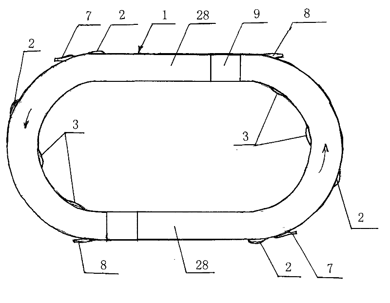
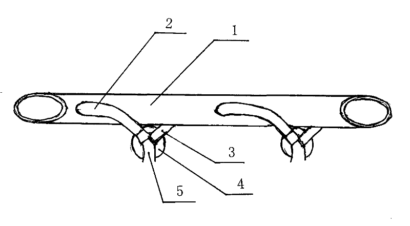
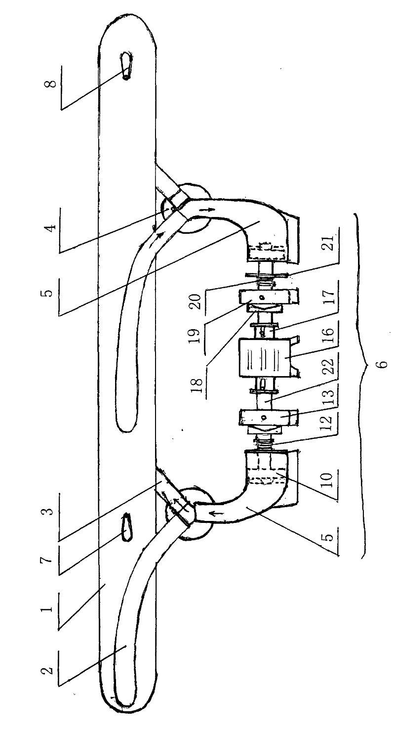
[0038] like figure 1 , figure 2 , image 3 As shown, the guided closed annular wind tunnel of the present invention includes an annular chamber 1, and the annular chamber 1 is an elliptical pipe structure, which is an elliptical shape formed by connecting two semicircular arcs with two common tangent lines. tube annulus. The tube wall of the annular chamber 1 is provided with a plurality of exhaust ports 7, a plurality of gas injection ports 8 and a plurality of airtight hatches 9; Correspondingly and tangentially arranged on the side walls are multiple pairs of air guide tubes 2 and return air tubes 3 communicating with the annular chamber 1, and the other ends of each pair of air guide tubes 2 and return air tubes 3 are connected to a three-way body 4. A group of power guiding devices 6 is connected between two adjacen...


PUM


Abstract

The invention discloses a guided and closed annular wind tunnel which is provided with an annular chamber with an oval tube structure. The tube wall of the annular chamber is provided with a pluralityof air exhaust openings, air injection openings and sealed hatch doors, wherein a plurality of pairs of air-guide tubes and air-return tubes, communicated with the annular chamber, are arranged correspondingly and tangentially on two side walls of arc-shaped tube walls at both ends of the oval annular chambers in major axis. The other end of each pair of air-guide tube and air-return tube is connected with a three-way body. Every two adjacent three-way bodies, connected with the air-guide tube and the air-return tube, are connected with a power guide device. The air-guide tubes are arranged on the annular chamber in the same direction as the set airflow direction; the air-return tubes are arranged on the annular chamber in a direction opposite to the set airflow direction. The wind tunnelhas simple structure, can obtain continuous accelerating force, provide a plurality of modes simulating the flow velocity, flow line, flow volume, heat and pressure of actual flow fields, and is notlimited in the experiment period. The invention has relatively high efficiency, energy conservation and environmental protection.

Description

technical field [0001] The invention relates to an experimental wind tunnel, in particular to a guided closed annular wind tunnel which can provide various flow velocities, streamlines, flows, etc. for simulating the actual flow field. Background technique [0002] A wind tunnel is a pipe-shaped experimental device that can artificially generate and control airflow to simulate the flow of air around an aircraft or object, measure the effect of airflow on an object and observe physical phenomena. It is aerodynamic The most commonly used and most effective tool for experimentation. Wind tunnel experiments are an indispensable part of aircraft development. It not only plays an important role in the research and development of aviation and aerospace engineering, but with the development of industrial aerodynamics, it is also more and more widely used in transportation, housing construction, wind energy utilization and environmental protection. [0003] Wind tunnels are divide...

Claims


Application Information

Patent Timeline
Patent Type & Authority Patents(China)
IPC IPC(8): G01M9/02G01M9/04
Inventor 王竹泉王嘉王竹雄
Owner 王竹泉
Why Eureka
Try Eureka