Degradable three-machine redundancy fault-tolerant system

A fault-tolerant system and three-machine redundancy technology, which is applied in hardware redundancy for data error detection, response error generation, etc., can solve the problem that the reliability and working life of deep space detection cannot be achieved, and there is no failure of two machines at the same time Response ability, fault tolerance and life limitation and other issues, to achieve the effect of strengthening independence, reducing interconnection, and strong real-time performance

Inactive Publication Date: 2009-11-11
BEIHANG UNIV
View PDF0 Cites 73 Cited by
  • Summary
  • Abstract
  • Description
  • Claims
  • Application Information

AI Technical Summary

Problems solved by technology

[0002] Some critical occasions in aerospace and other fields require high availability of its subsystems and long working life, such as temperature control systems. For these applications, any loss caused by control system failure is unbearable of
The traditional dual-machine redundant control system has the following disadvantages: such as dual-machine hot backup, although it can reduce the switching time between the main and standby machines when a single machine fails, the working life of the system will be significantly reduced; dual-machine cold backup or warm backup , a...

Method used


Image

  • Degradable three-machine redundancy fault-tolerant system
  • Degradable three-machine redundancy fault-tolerant system
  • Degradable three-machine redundancy fault-tolerant system

Examples


Embodiment Construction

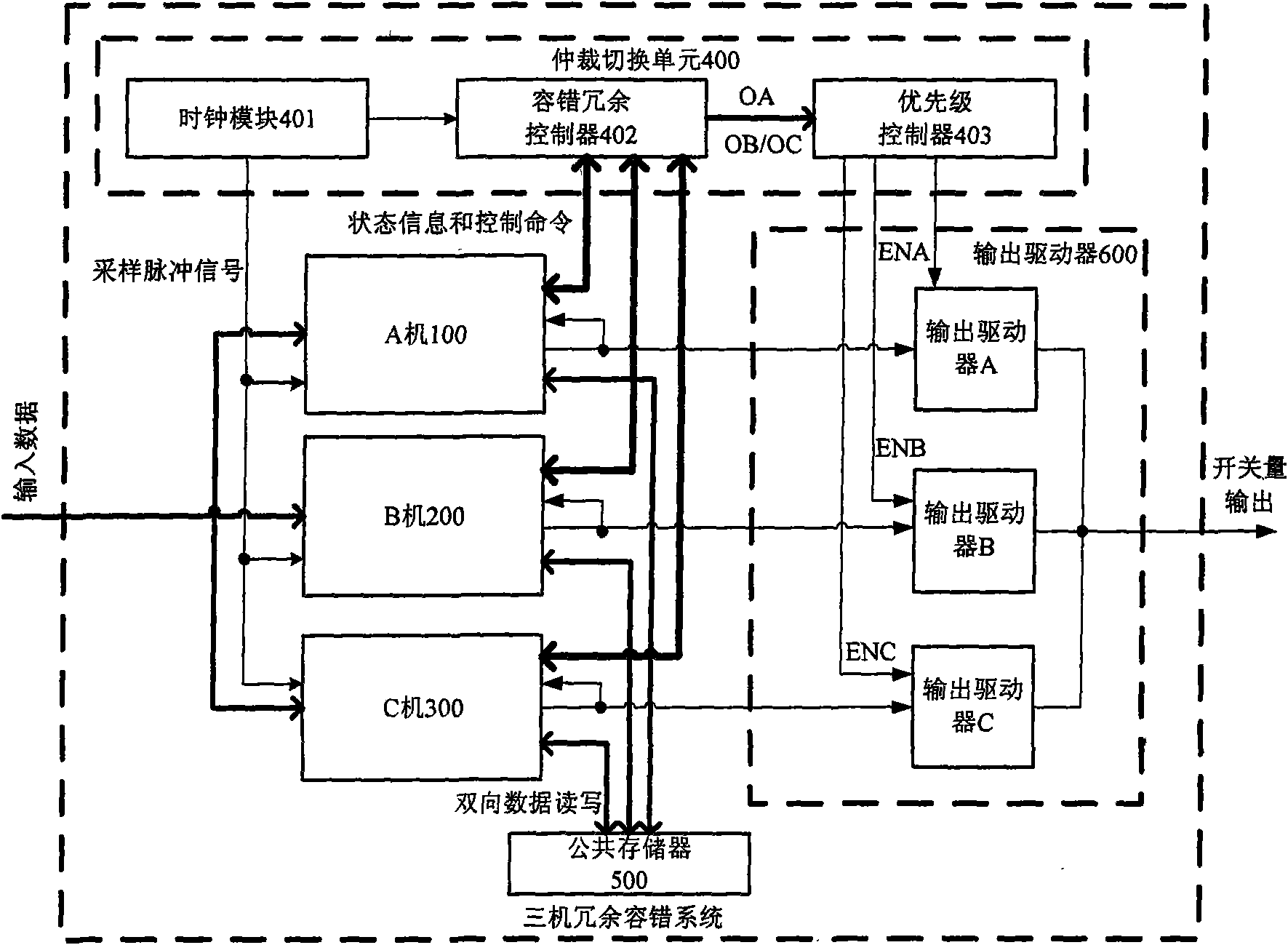
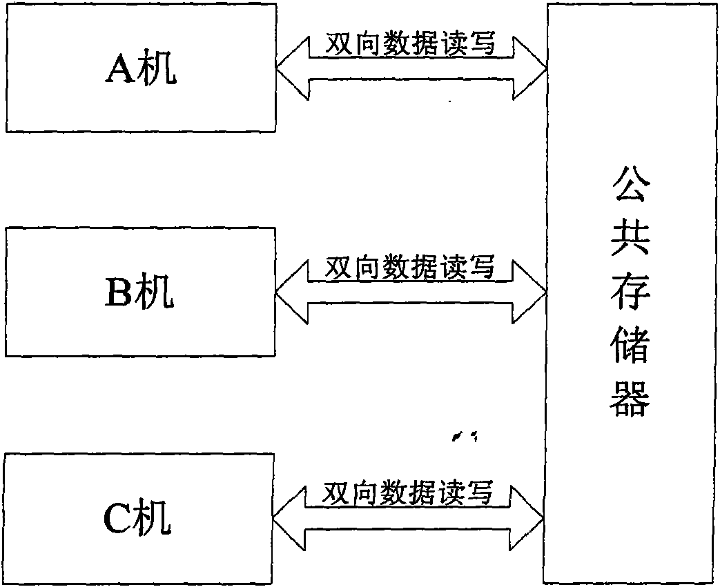
[0023] Such as figure 1 As shown, the present invention includes machine A 100 , machine B 200 , machine C 300 , arbitration switching unit 400 , public storage 500 , and output drivers 600 of three single machines.

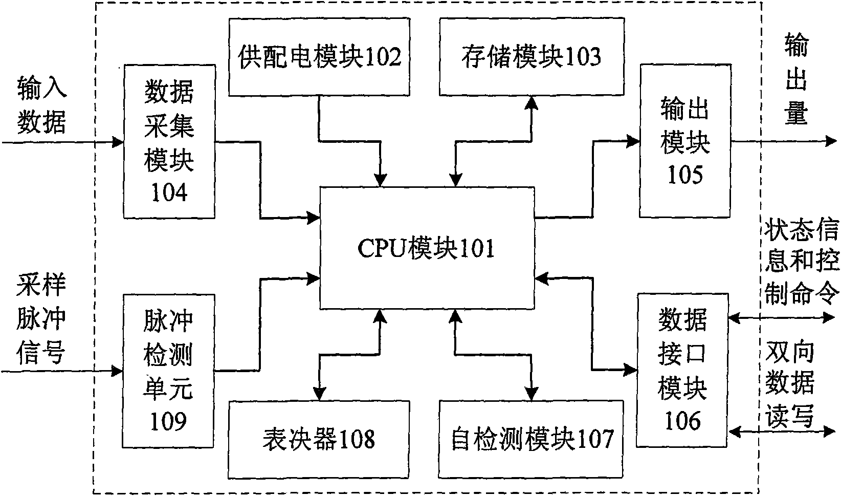
[0024] Such as figure 1 , 2 As shown, the A machine 100, the B machine 200, and the C machine 300 all have the same structure. Take machine A as an example: the hardware structure of machine A 100 includes: CPU module 101, power supply and distribution module 102, storage module 103, data acquisition module 104, output module 105 and data interface module 106; the software module includes: self-test module 107, A voter 108 and a pulse detection unit 109 . The main function of the power supply and distribution module 102 is to complete the operation of restarting the single machine or permanently powering off the single machine under the control of the arbitration switching unit 400 . The storage module 103 includes two parts, a program storage area and a data...


PUM


Abstract

A degradable three-machine redundancy fault-tolerant system consists of three single machines such as a machine A, a machine B, a machine C which have the same structure, a public memory, an arbitration switching unit, and the output drivers of the three machines; the machine A, the machine B and the machine C achieve the exchange of treatment results among the three machines by reading and writing the output results of the single machines in the public memory so as to conduct three-machine voting; in addition, the machine A, the machine B and the machine C can also achieve three-machine or dual-machine synchronization by reading and writing the process information in the public memory; the machine A, the machine B and the machine C are connected with each other so that any one machine can read the status information whether another party is in normal work currently; the machine A, the machine B and the machine C are also connected with the arbitration switching unit and provide self-status information for the arbitration switching unit, and the arbitration switching unit can conduct the redundancy degrading of three-machine work/dual-machine work/single-machine work and the redundancy system reconfiguration of three-machine work/dual-machine work/single-machine work, in addition, the arbitration switching unit is also connected with the output drivers of the three machines and decides the use right of the machine A, the machine B and the machine C to the output line; and as for the three machines in normal work, the output is provided with a priority order, namely the machine A-the machine B-the machine C in sequence. The invention has the advantages of high reliability and long service life.

Description

technical field [0001] The invention relates to an embedded three-machine redundant backup technology, in particular to a degradable three-machine redundant fault-tolerant system. Background technique [0002] Some critical occasions in aerospace and other fields require high availability of its subsystems and long working life, such as temperature control systems. For these applications, any loss caused by control system failure is unbearable of. The traditional dual-machine redundant control system has the following disadvantages: such as dual-machine hot backup, although it can reduce the switching time between the main and standby machines when a single machine fails, the working life of the system will be significantly reduced; dual-machine cold backup or warm backup , although a longer working life can be obtained, the system recovery time is relatively long when a single machine fails, and the above two schemes cannot meet the reliability and working life required by...

Claims


Application Information

Patent Timeline
IPC IPC(8): G06F11/18
Inventor 徐利杰王青董朝阳陈威
Owner BEIHANG UNIV
Why Eureka
Try Eureka