
Shielding device and manufacturing method thereof

A technology of shielding device and manufacturing method, applied in the direction of magnetic/electric field shielding, electrical components, etc., can solve problems such as difficult to cooperate well, increase assembly clearance, occupy side space of shielding cover, etc.

Active Publication Date: 2011-06-22
莱尔德电子材料(深圳)有限公司
View PDF1 Cites 0 Cited by
  • Summary
  • Abstract
  • Description
  • Claims
  • Application Information

AI Technical Summary

Problems solved by technology

[0006] In the above structure, since the buckle or protrusion is located on the side of the cover of the shielding case and the side of the corresponding frame, after the cover and the frame are assembled, the side of the cover needs to partially overlap with the side of the frame so that the card snaps or tabs, thus occupying space on the sides of the shield when assembled
Moreover, although a plurality of buckles or protrusion structures are arranged on the side of the cover and the side of the frame, after the cover is engaged with the frame, there will still be an assembly gap between the buckles and the protrusions. Especially for the snap-fit ​​connection of multiple buckles and protrusions, it is difficult to ensure a good fit at each snap position, and poor fit may occur at some buckles or protrusions, which may increase the Assembly gap, so it is difficult to achieve zero assembly gap at the junction of the assembled cover and frame, and the existence of these assembly gaps will weaken the grounding and shielding performance of the shield, which may cause PF leakage

Method used


Image

  • Shielding device and manufacturing method thereof
  • Shielding device and manufacturing method thereof
  • Shielding device and manufacturing method thereof

Examples


Embodiment Construction

[0032] The details of the specific embodiments of the present invention will be described in detail below with reference to the accompanying drawings. However, it should be noted that the following description is merely exemplary in nature, and is not intended to limit the disclosure, application, or use of the present invention.

[0033] In the description, certain terms used herein are for reference only, and therefore are not meant to be limiting. For example, terms such as "upper", "lower", "above", "below", "top" and "bottom" refer to directions in the drawings to which reference is made. Terms such as "front", "backward", "rear", "bottom" and "side" describe the orientation of each part of a component in a consistent and arbitrary frame of reference, and describe the component in question by contrast The text and related drawings can make this frame of reference clear. Such terms may include the words exactly described above, their derivatives, and words with similar mean...


PUM

PropertyMeasurementUnit
heightaaaaaaaaaa
depthaaaaaaaaaa
wavelengthaaaaaaaaaa

Abstract

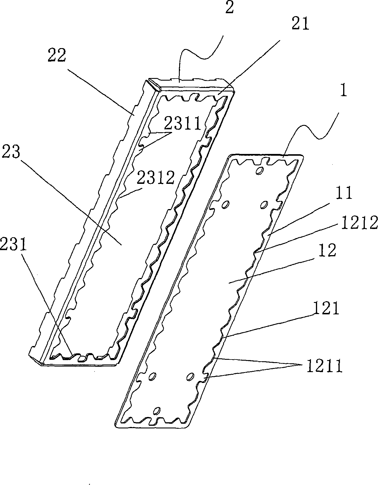
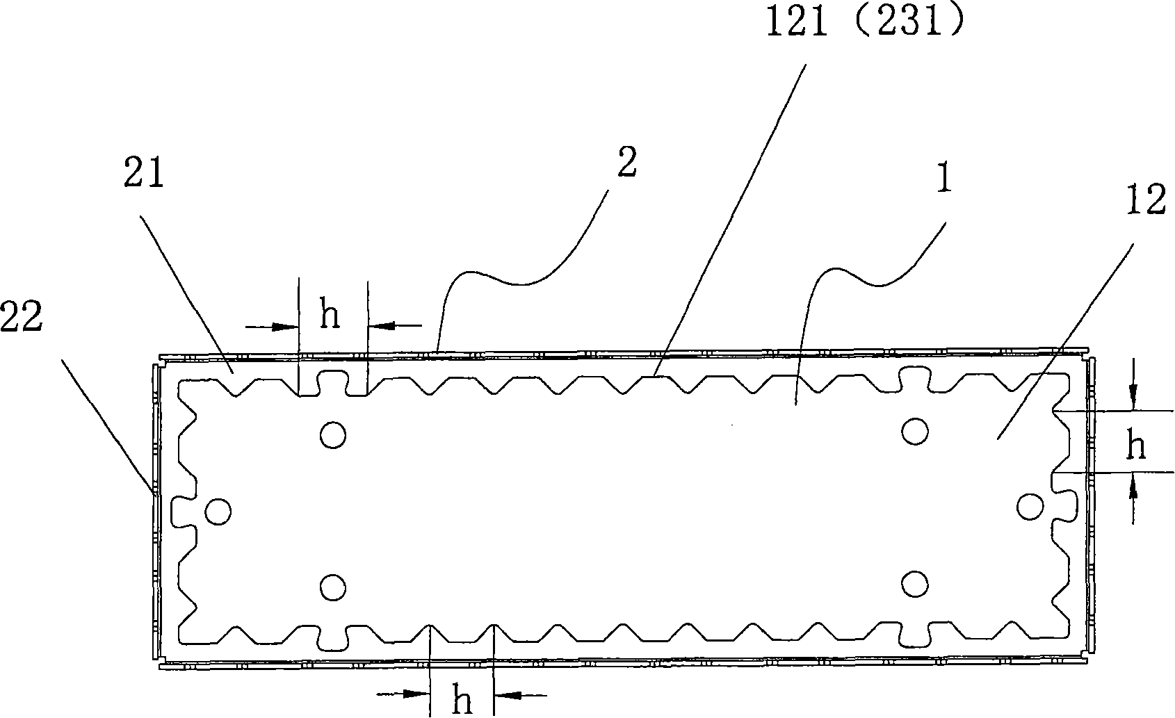
The invention provides a shielding device and a manufacturing method thereof. The shielding device comprises a plate-like cover and a frame, wherein the cover is provided with a top which is provided with at least one projected joint part projecting towards the frame; the frame is provided with a top and a side edge which downwards extends from the top, the top is provided with at least one joint interface corresponding to the projected joint parts of the cover, and the peripheral outline of each joint interface is the same as the peripheral outline of the corresponding projected joint part; and the projected joint part of the cover is jointed with the corresponding joint interface of the frame in an interference extrusion way to form an assembling structure of the cover and the frame. With the shielding device and the manufacturing method thereof, no side edge of the cover needs to be manufactured, thus the side edge space of the shielding device is prevented from being occupied, the cost of materials for manufacturing the side edge of the cover is saved, and zero fit-up gap is realized between the cover and the frame so that the grounding property and the shielding property of the shieldingdevice are ensured.

Description

Technical field [0001] The present invention generally relates to an electromagnetic interference (EMI) shielding device and a manufacturing method thereof, and more particularly to a shielding device suitable for providing electromagnetic interference shielding for one or more electrical components on a substrate and a manufacturing method of the shielding device method. Background technique [0002] The description in this section only provides background information related to the disclosure of the present invention, and does not constitute prior art. In normal operation, the electronic / electrical components in the equipment usually generate undesirable electromagnetic energy, which can interfere with the operation of adjacent electronic / electrical components due to the transmission of EMI generated by radiation. In order to eliminate or at least mitigate the negative effects caused by electromagnetic interference, shielding covers / devices can be used to provide electromagnet...

Claims


Application Information

Patent Timeline
Patent Type & Authority Patents(China)
IPC IPC(8): H05K9/00B21D28/10B21C23/02
CPCH05K9/0032Y10T29/49002
Inventor 沈国良
Owner 莱尔德电子材料(深圳)有限公司
Learn More