Electric power feeding system

An electric power supply and electric power technology, applied in electric traction, circuits, motors, etc., can solve the problems such as the decrease in the responsiveness of the output power and the delay in the response of the gas supply

Inactive Publication Date: 2009-11-11
TOYOTA JIDOSHA KK
View PDF0 Cites 12 Cited by
  • Summary
  • Abstract
  • Description
  • Claims
  • Application Information

AI Technical Summary

Problems solved by technology

The fuel cell controls the supply of fuel gas to output power according to the demand, but the responsiveness of the output power may decrease due to the delay in the response of the gas supply.

Method used


Image

  • Electric power feeding system
  • Electric power feeding system
  • Electric power feeding system

Examples


Embodiment 1

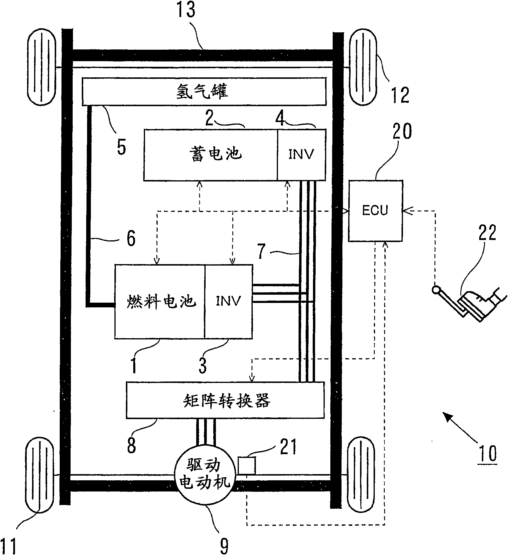
[0028] figure 1 Schematically shows a vehicle 10 equipped with a fuel cell system as an electric power supply system of the present invention, and a mobile body that uses electric power supplied by the fuel cell system as a drive source. A vehicle 10 has a front drive wheel 11 and a rear drive wheel 12 mounted on a vehicle body frame 13, and the front drive wheel 11 is driven by a drive motor (hereinafter simply referred to as "motor") 9 thereby Self-propelled (self-propelled), able to move. The electric motor 9 is a so-called three-phase AC motor, and is supplied with electric power from the fuel cell 1 and the battery 2 , and these fuel cells 1 and the battery 2 are stably fixed to the vehicle body frame 13 .

[0029] The fuel cell 1 is supplied with hydrogen as a fuel gas and air as an oxidizing gas from a hydrogen tank 5 via a hydrogen supply passage 6 and supplies air as an oxidizing gas from an air supply device (not shown), and generates electricity by electrochemical ...

Embodiment 2

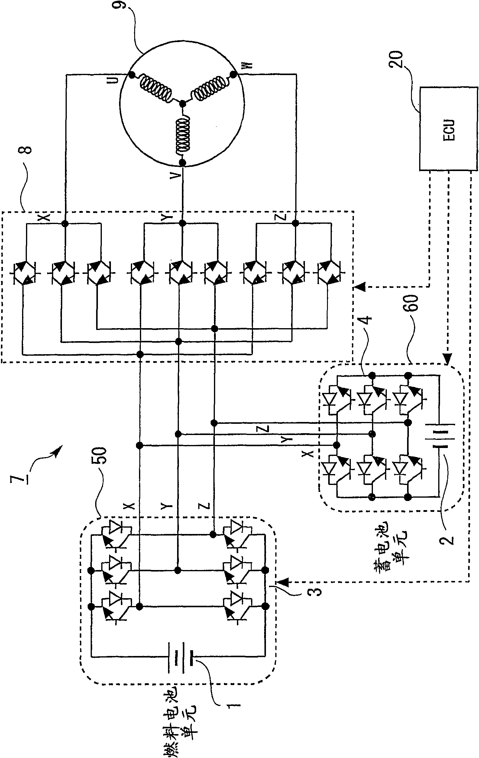
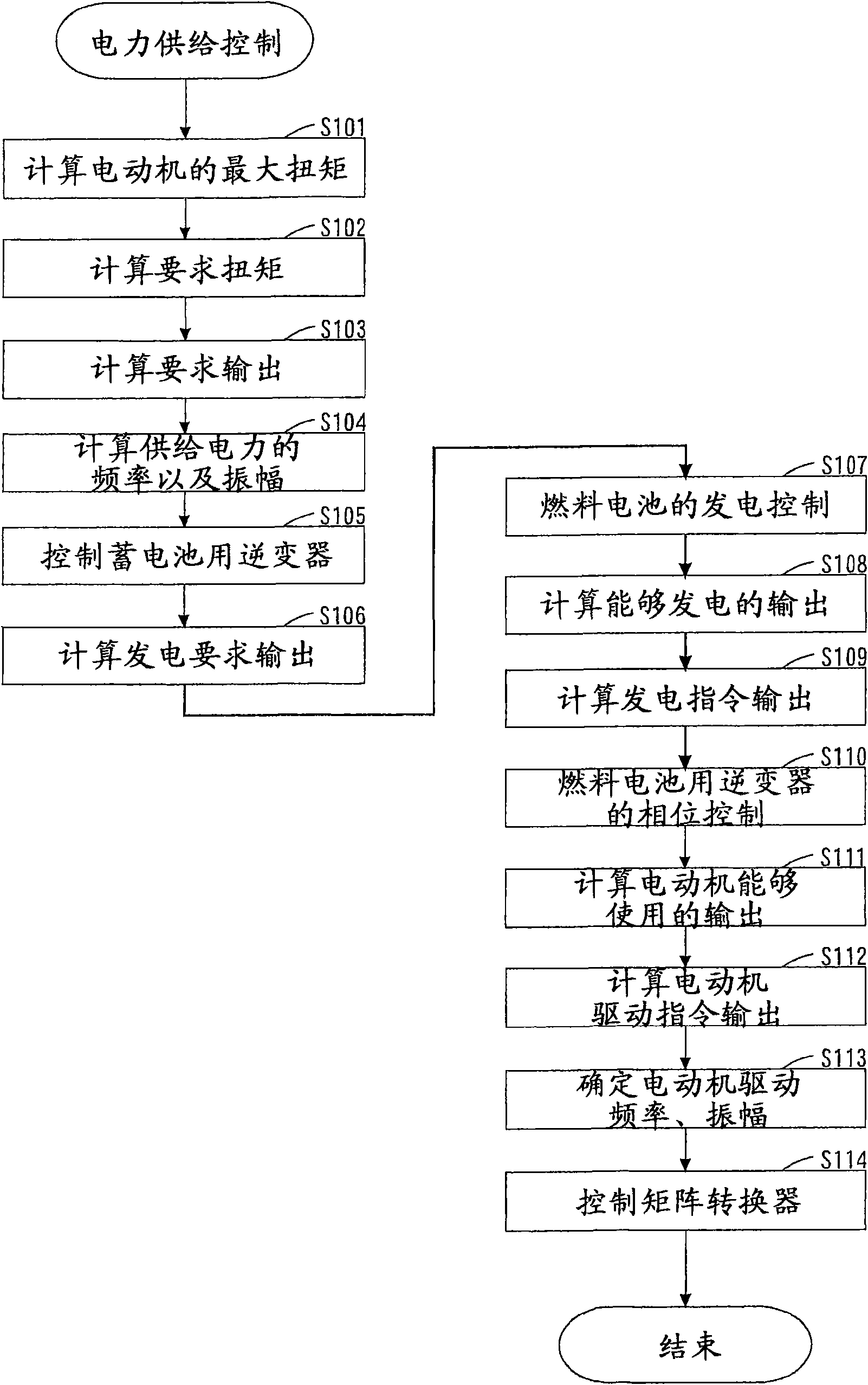
[0052] for image 3 Other embodiments of the power supply control shown are described. In the above-mentioned embodiment, in order to determine the output distribution of the fuel cell 1, the phase difference of the AC output from the fuel cell unit 50 relative to the AC output from the battery unit 60 is controlled, but in this embodiment, the phase difference is set to zero, thereby setting the output from the fuel cell 1 to zero. In this way, only the AC output from the battery unit 60 whose output is controlled in S105 is supplied to the electric motor 9, so that the power generation of the fuel cell 1 can be stopped.

[0053] This control of the phase difference is performed from the ECU 20 to the fuel cell inverter 3 when it is desired to stop the power generation of the fuel cell 1 and drive the vehicle 10 only with the charge energy of the battery 2 .

[0054] As described above, according to the power supply system of the present invention, in the power supply syste...


PUM


Abstract

Provided is an electric power feeding system, which is mounted on a mobile unit (10) for feeding an electric power from a plurality of DC power source devices (1 and 2) to an AC drive device (9) to function as a drive source of the mobile unit (10). The plural DC power source devices are individually connected with corresponding inverters (3 and 4) for converting the DC outputs into alternating currents. Each DC power source device and a corresponding inverter constitute one AC output unit. the AC output unit outputs an AC output to the outside. The connections between each AC output unit and the AC drive device and between the individual AC output units are made by AC wiring lines (7). In case the electric power is fed from the plural DC power source devices to the AC drive device, therefore, it is possible to keep the insulation relatively easily between the power feeding wiring lines and the mobile unit and to connect the DC power source devices conveniently.

Description

technical field [0001] The present invention relates to an electric power supply system for supplying electric power to a driving device, for example, a system for supplying electric power to a driving device from a fuel cell that generates electric power through an electrochemical reaction. Background technique [0002] In recent years, fuel cells have attracted attention as power sources excellent in operating efficiency and environmental friendliness. The fuel cell controls the supply amount of fuel gas to output electric power in accordance with the demand, but the responsiveness of the output power may decrease due to the delay in the response of the gas supply amount. Therefore, the fuel cell and the battery (power storage device) are connected in parallel to form a power supply, and the output voltage of the fuel cell is converted by a DC-DC converter (DC-DC converter), thereby realizing the battery and fuel cell. and use. Then, the DC power supplied from both is co...

Claims


Application Information

Patent Timeline
Patent Type & Authority Applications(China)
IPC IPC(8): B60L11/18H01M8/00H02J7/00H02J7/34H02M5/257H02M7/48
CPCY02T10/7066Y02T90/34B60L2240/423Y02T10/725H01M16/006B60L2210/20B60L11/1803B60W2710/083B60L11/1868B60W20/00B60L15/007B60L11/1887Y02T10/642B60W10/08B60L2200/26B60L50/51B60L58/20B60L58/40Y02E60/10Y02E60/50Y02T10/64Y02T10/70Y02T10/72B60W10/26B60W20/10B60W2710/242Y02T90/40
Inventor 滨田研一北村伸之
Owner TOYOTA JIDOSHA KK
Why Eureka
Try Eureka