

Pulse frequency modulation circuit based on voltage controlled oscillator
A pulse frequency modulation, voltage controlled oscillator technology, applied in the field of electronics, can solve the problems of high output ripple, large frequency change range, slow clock, etc., to achieve the effect of reducing ripple and stable cycle
Active Publication Date: 2016-02-17
SPREADTRUM COMM (SHANGHAI) CO LTD
View PDF7 Cites 1 Cited by
- Summary
- Abstract
- Description
- Claims
- Application Information
AI Technical Summary
Problems solved by technology
[0002] The pulse frequency modulation method adjusts the duty cycle of the clock by changing the frequency of the clock. When the output load is small, the clock frequency is high and the duty cycle becomes small. When the load becomes large, the clock becomes very slow. Significant changes may occur during the working process of the entire circuit. The pulse frequency modulation circuit of the prior art has a relatively large range of frequency changes, and the ripple of the output voltage will also change significantly with the change of the clock frequency. The control method does not ideal
In the prior art, when the load is light, the switching power converter can automatically switch to a low power consumption mode to minimize battery current consumption, by intermittently sending out pulse signals to achieve constant frequency by reducing the switching times, increase the duty cycle to improve light load and standby efficiency, the waveform of the pulse modulation signal PFM1 in this mode is as follows figure 1 As shown, however, this method will also cause high output ripple, and the control method is not ideal
Method used
View moreImage
Smart ImageViewing Examples


Examples
specific Embodiment
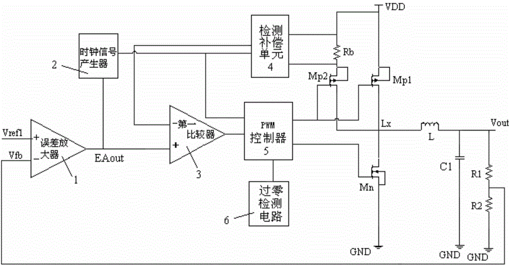
[0067] In a specific embodiment, the feedback network includes a first resistor R1 and a second resistor R2 connected in series, and the feedback voltage signal is drawn from a node where the first resistor R1 and the second resistor R2 are connected.
[0068] As a preferred embodiment of the present invention, the current detection circuit includes:
[0069] A detection resistor Rb, connected in series with the current detection circuit;
[0070] A detection compensation unit 4, connected to both ends of the detection resistor Rb, to detect the current flowing through the detection resistor;
[0071] A detection control switch Mp2 controlled on and off by the pulse modulation signal is connected to the current detection circuit.
Login to View More PUM
 Abstract
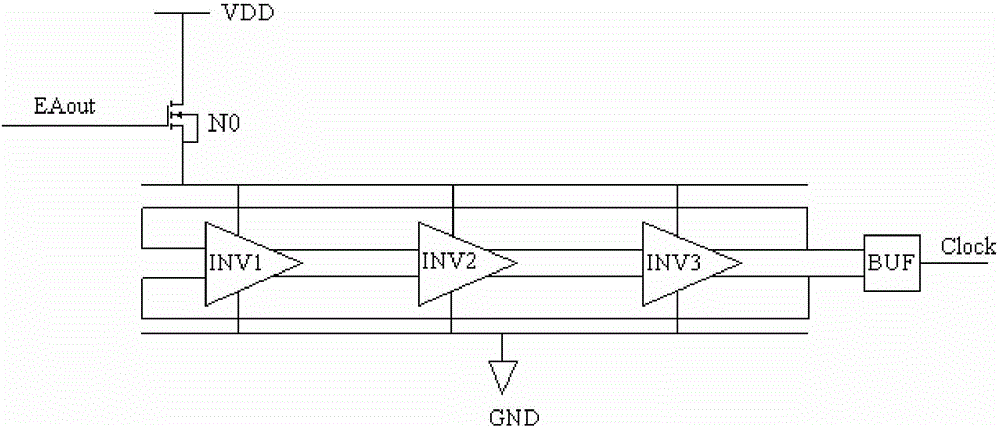
The invention discloses a pulse frequency modulation circuit based on a voltage controlled oscillator, and relates to a switch power supply circuit. The pulse frequency modulation circuit comprises a work circuit which is switched between a charge mode and a discharge mode under the effect of pulse modulation signals; a control circuit which generates the pulse modulation signals according to first reference voltages, voltage feedback signals and frequency variable clock signals and comprises an error amplifier providing error amplification signals; a clock signal generator which comprises an annular oscillation unit generating clock signals with fixed frequencies under the effect of power supply voltages; and an adjustment unit which is connected between the power supply voltages and the annular oscillation unit for adjusting work currents of the circuit under the effect of the error amplification signals so as to adjust the clock signals. According to the invention, the size of the work currents of the clock signal generator is adjusted through the error amplification signals, the oscillation frequency is changed, the frequency of the clock signals is finally adjusted, needed pulse modulation signals are obtained, the cycle is stable, and ripples of output voltages are reduced.
Description
technical field [0001] The invention relates to the field of electronic technology, in particular to a switching power supply circuit. Background technique [0002] The pulse frequency modulation method adjusts the duty cycle of the clock by changing the frequency of the clock. When the output load is small, the clock frequency is high and the duty cycle becomes small. When the load becomes large, the clock becomes very slow. Significant changes may occur during the working process of the entire circuit. The pulse frequency modulation circuit of the prior art has a relatively large range of frequency changes, and the ripple of the output voltage will also change significantly with the change of the clock frequency. The control method does not ideal. In the prior art, when the load is light, the switching power converter can automatically switch to a low power consumption mode to minimize battery current consumption, by intermittently sending out pulse signals to achieve con...
Claims
Login to View More Application Information
Patent Timeline
 IPC IPC(8): H02M3/156
Inventor樊茂
OwnerSPREADTRUM COMM (SHANGHAI) CO LTD