
Changing device for molds for building block forming machine

A technology of a block forming machine and a conversion device, which is applied to ceramic forming machines, cranes, manufacturing tools, etc., can solve problems such as inconvenience, work-related accidents and economic losses, and narrow installation space for block forming machines and supporting facilities.

Inactive Publication Date: 2009-11-18
山东高唐华通液压机械有限公司
View PDF0 Cites 2 Cited by
  • Summary
  • Abstract
  • Description
  • Claims
  • Application Information

AI Technical Summary

Problems solved by technology

The mold is made of steel, which is generally heavy. The weight of the upper mold and the lower mold is about 1.5-2 tons. Moreover, for the convenience of production, the installation of the block forming machine and supporting facilities is relatively compact and the space is narrow. Replacing the mold is not only time-consuming and laborious, but also extremely difficult. It is inconvenient, relying on manpower alone will not work hard, some facilities need to be dismantled temporarily to make room for the disassembly and installation of the mold, it will take a long time, affect production, and it is extremely unsafe, there is a great danger, and it is easy to cause industrial accidents and economic loss

Method used


Image

  • Changing device for molds for building block forming machine
  • Changing device for molds for building block forming machine
  • Changing device for molds for building block forming machine

Examples


Embodiment Construction

[0010] The specific embodiments of the present invention will be further described below in conjunction with the accompanying drawings.

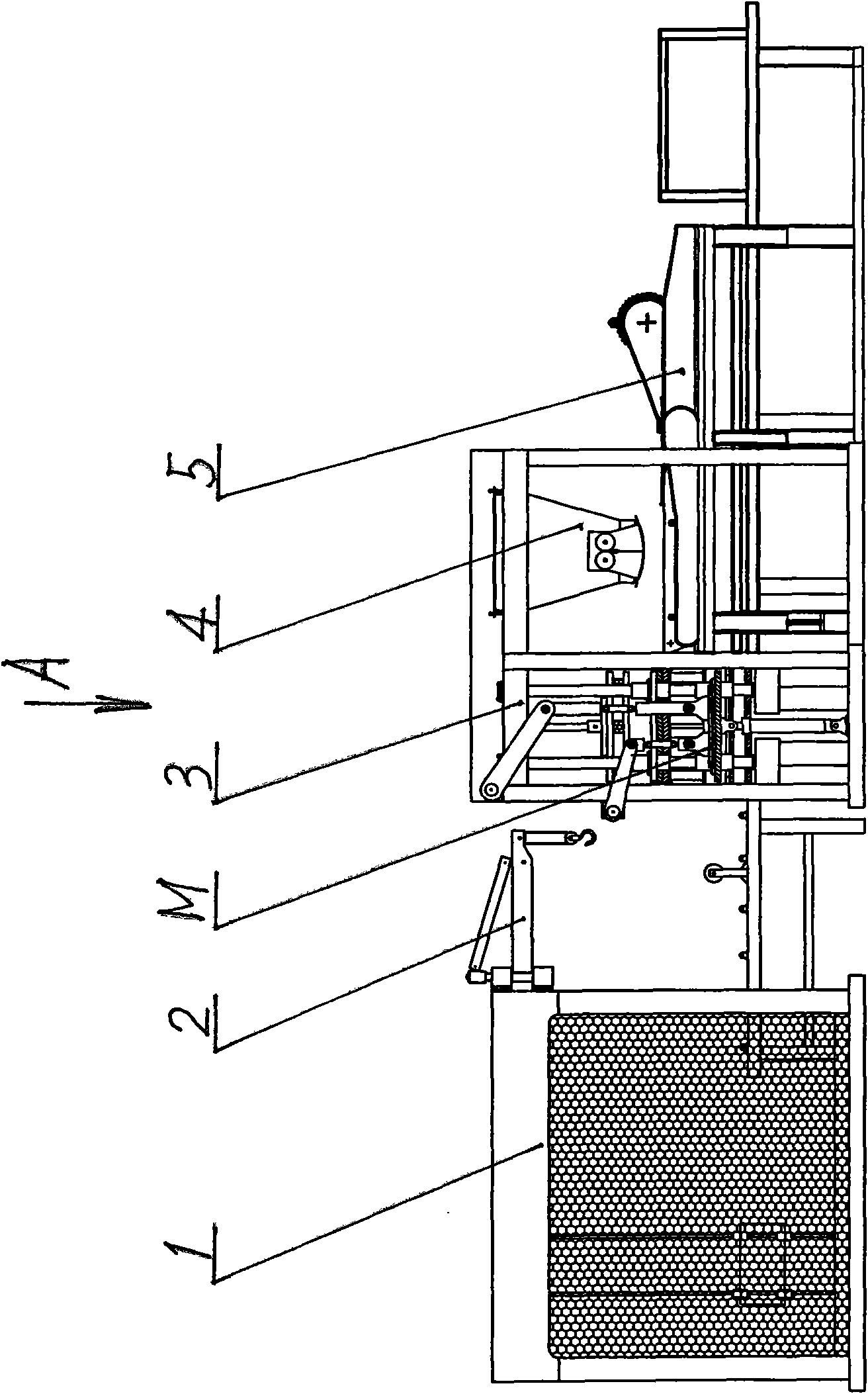
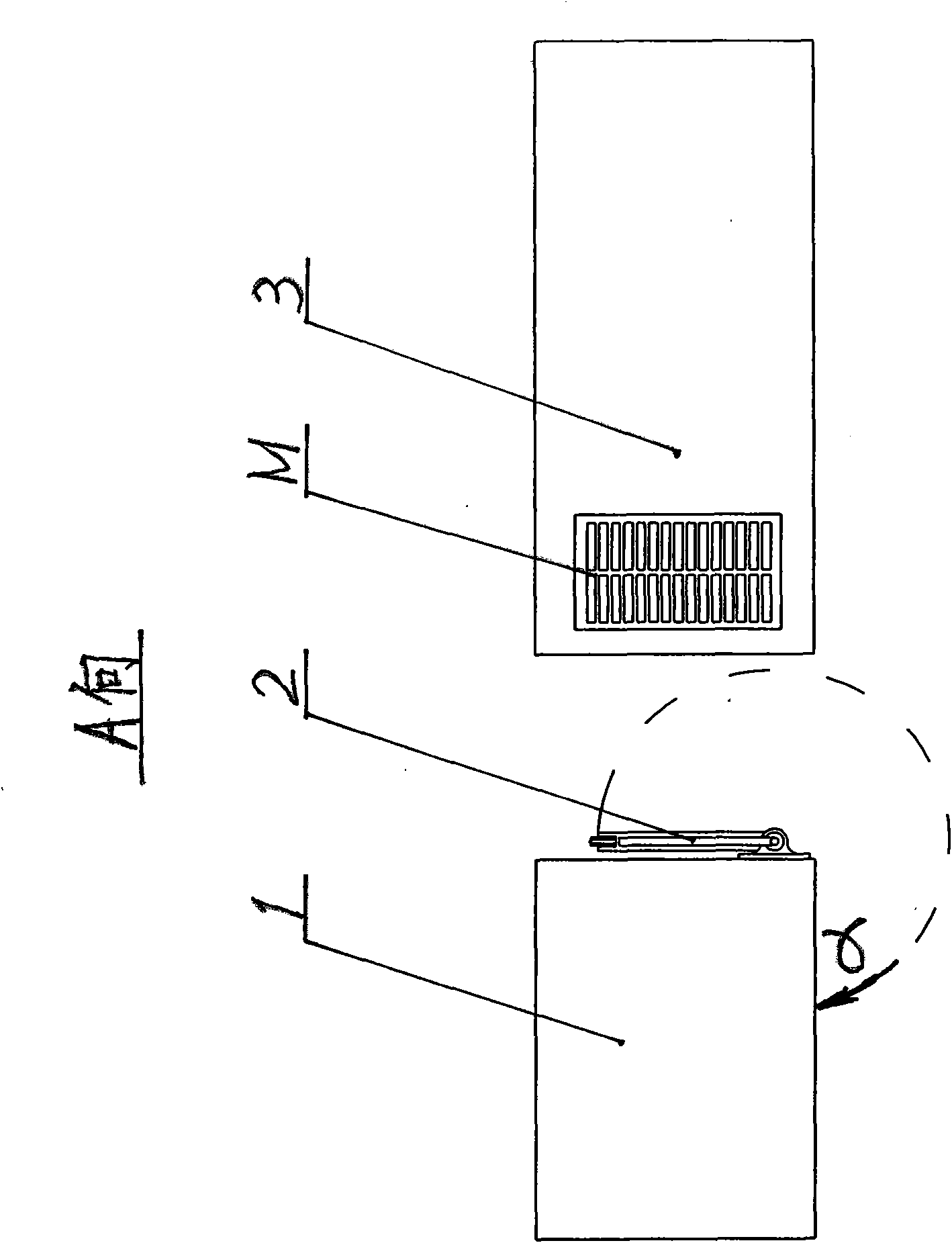
[0011] refer to figure 1 , the rear of the block forming machine 3 is connected to the feeding funnel 4 and the material distribution mechanism 5, the distance between the block forming machine 3 and the stacking machine 1 is very close, and the structure is compact, and the front of the stacking machine 1 facing the block forming machine 3 The upper part of the panel is equipped with a mold conversion device 2

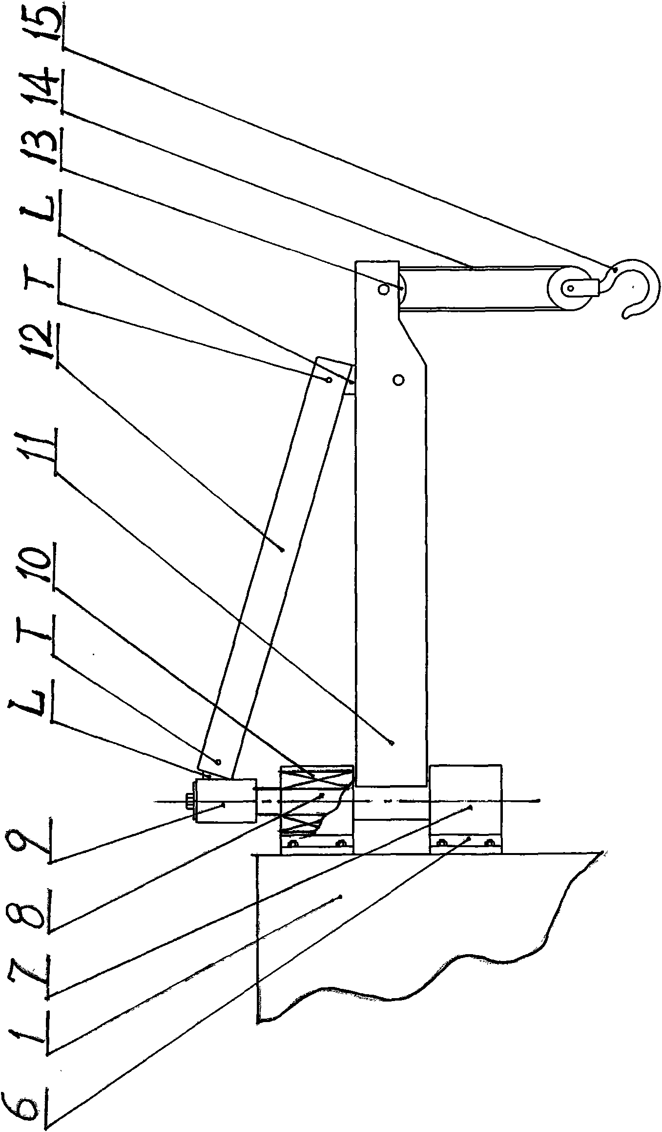
[0012] refer to figure 2 , the structure of the mold conversion device 2 includes: connecting base 6, fixed shaft seat 7, rotating vertical shaft 8, rotating shaft sleeve 9, lifting arm 11, diagonal stay rod 12, steel wire rope 14, pulley hook 15, connecting and fixing on the stack On the top of the front panel of the trigger 1, the fixed shaft seat 7 is equipped with a pressure bearing 10, and the outside is fixedly connected ...


PUM


Abstract

The invention discloses a changing device for molds for a building block forming machine. In the changing device, fixed shaft seats (7) are fixed on the upper part of a palletizing machine (1) through a connecting base (6), a rotating vertical shaft (8) is sleeved in a pressure bearing (10) arranged in the fixed shaft seats (7), the upper part of the rotating vertical shaft (8) is sleeved with a rotating shaft housing (9), the inner end of a hoisting arm (11) is arranged between the upper and lower fixed shaft seats (7), the outer end of the hoisting arm (11) is connected with the rotating shaft housing (9) through a diagonal draw bar (12), and an outer end hoisting pulley (13) is connected with a pulley hook (15) through a steel rope (14). In normal time, the hoisting arm (11) is rotated and tightly attached to the plane of the palletizing machine (1), but is rotated to a position in front of a building block forming machine (3) when a mold (M) is to be changed, so that the pulley hook (15) can first hook the mold (M) and drive the hoisting arm (11) to rotate on the rotating main shaft (8) to remove the mold (M) from a main machine, and then hook a new mold (M) and drive the hoisting arm (11) to rotate on the rotating main shaft (8) to place the new mold (M) on a specific position of the building block forming machine (3). The changing device has the advantages of quick change, high working efficiency and high safety.

Description

technical field [0001] The invention relates to a block forming machine, in particular to a replacement method of a block mould. Background technique [0002] At present, unburned brick machines and block forming machines use waste brick slag, cement slag, and slag to press blocks, which play a very good role in protecting cultivated land, saving energy, reusing waste, and preventing environmental pollution. Unburned bricks and masonry Blocks are used more and more widely. According to the different needs of users, the model and specification of the production blocks are determined, and various blocks are produced by changing the mold. Especially for large-scale automatic block forming machines, the blocks to be produced have different specifications and many varieties, and the molds often need to be replaced to meet the requirements of block production. The mold is made of steel, which is generally heavy. The weight of the upper mold and the lower mold is about 1.5-2 tons....

Claims


Application Information

Patent Timeline
IPC IPC(8): B28B3/00B66C23/02B66C23/62B66C23/64
Inventor 冯伟冯利
Owner 山东高唐华通液压机械有限公司
Learn More