
Branched accelerating device

An accelerator, bifurcated technology used in transportation and packaging, ship propulsion, ship components, etc.

Inactive Publication Date: 2009-11-18
BEIJING XINXUANSHIWEI TECH
View PDF0 Cites 0 Cited by
  • Summary
  • Abstract
  • Description
  • Claims
  • Application Information

AI Technical Summary

Problems solved by technology

[0002] There is not a good non-energy acceleration in the existing hull

Method used


Image

  • Branched accelerating device
  • Branched accelerating device
  • Branched accelerating device

Examples


Embodiment Construction

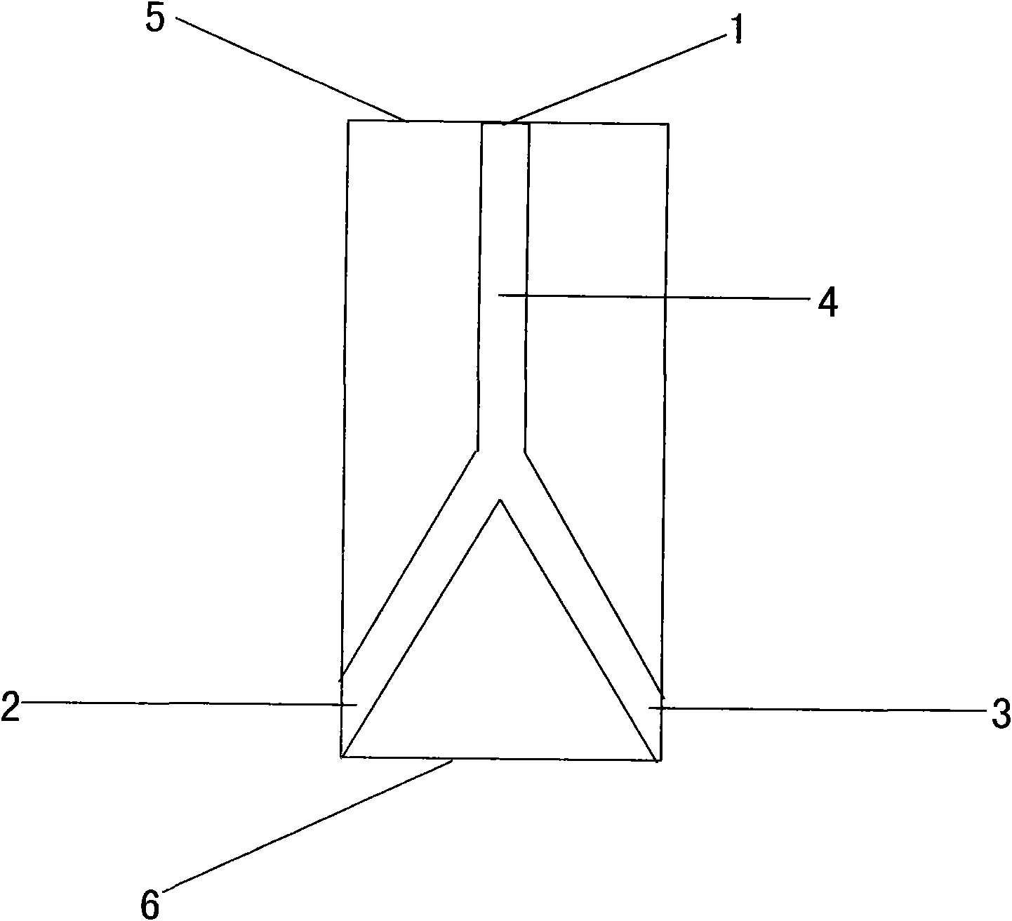
[0055] refer to figure 1 is a diagram of an accelerated plumbing installation with a bifurcated drainpipe installation.

[0056] Wherein 1 is water inlet pipe device.

[0057] Wherein 2 is the left side discharge port of the bifurcated drainpipe device, which is used to discharge water to the rear of the ship to speed up the ship.

[0058] Wherein 3 is the right side discharge port of the bifurcated drainpipe device, is used for draining water to the rear of the ship, so that the ship can be accelerated.

[0059] Wherein 4 is the trunk device of drainpipe, is used for supporting bifurcated drainpipe device.

[0060] 5 of them are bows.

[0061] 6 of them are stern.

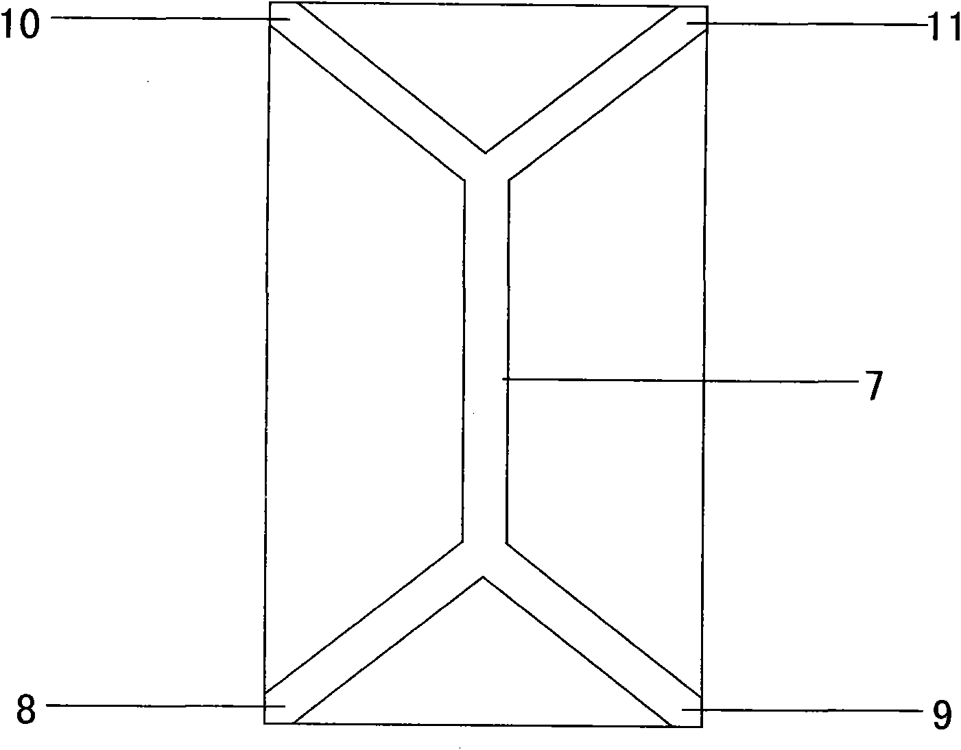
[0062] refer to figure 2 It is a speed up drain set with a split drain set and a split intake set, used to increase the speed of the boat by draining water to the split drain set at the rear of the vessel.

[0063] Wherein 7 is the trunk device of drainpipe, is used for supporting bifurcated drainpipe devic...


PUM


Abstract

The invention relates to a branched accelerating device. A ship is internally provided with an accelerating drainpipe; the accelerating drainpipe is internally provided with a trunk drainpipe; the trunk drainpipe is internally provided with at least one branch water inlet pipe and at least one branch drainpipe; and water is drained to the rear part of the ship by the branch drainpipe so as to increase the sailing speed of the ship. Because the branch drainpipe and the branch water inlet pipe are arranged, the accelerating drainpipe of the ship is provided with multi-stage units, and stronger ship propelling force is generated.

Description

technical field [0001] The invention belongs to the field of ships, in particular to a bifurcation acceleration device. Background technique [0002] There is not a good non-energy acceleration device in the existing hull. Contents of the invention [0003] The technical problem to be solved by the present invention is to provide a way to accelerate the ship by using a bifurcated pipeline. By installing the bifurcated acceleration pipeline on the ship, the acceleration pipeline will move the hull of the ship under the action of the water flow thrust of the bifurcated navigation pipeline. Push forward to make the hull accelerate in the state of non-energy, without adding new energy under the premise of improving the environmental protection effect, so that the ship can increase the forward power. [0004] When the water flow acceleration pipeline is installed in the boat, if the bifurcated pipeline is set, the water collected by the boat can be diverted to a plurality of w...

Claims


Application Information

Patent Timeline
IPC IPC(8): B63H11/02
Inventor 李辰宇
Owner BEIJING XINXUANSHIWEI TECH
Learn More